A
"Men have become the tools of their tools"
Henry David Thoreau (1817-1862)
During the research for this dissertation, wearable computers have evolved from very simple and slow 2D graphics to highly detailed 3D rendering systems capable of video overlay, texture mapped triangles, and the ability to render millions of triangles per second for realistic AR output. As discussed in the previous chapter, this evolution process is ongoing as various devices are improved by their respective manufacturers. This appendix discusses the numerous mobile outdoor AR systems that I have constructed at key points in their development, broken down into the equipment that was used, how it was mounted onto the user, and the software that was developed for the platform. Since these three categories were not all changed at the same time (the same software may have been used with multiple types of equipment), platforms are described at various important milestones of development.
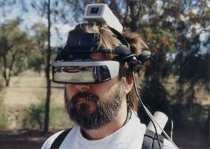
The first prototype system I worked on the development of was named Map-In-The-Hat [THOM98] [PIEK99a], with the objective being to develop a mobile navigation system that could guide users towards waypoints in unfamiliar terrain. This system could also be referred to as the Tinmith-I prototype since further designs were named after this, although it was never referred to in any literature using this name. Although the computer used was designed for mounting on a belt, there were too many components to carry and so a ruck sack was used instead. While this system was used for several informal studies, the wearable computer had faulty video hardware that caused it to run very slow, and the GPS did not reliably receive satellite signals.
A.1.1
Equipment
|
|

An initial collection of equipment was supplied by DSTO and was used for this initial evaluation. This initial equipment included the following:
· Phoenix 486 belt mounted wearable computer (16 mb memory, 500 mb hard drive, 640x480x4bpp VGA output @ 2 Hz - see Figure A‑1)
Precision Navigation TCM2 magnetic compass (15 Hz updates)
Trimble SVeeSix GPS with radio-based differential receiver (1 Hz updates at 5-10 metres accuracy)
Sony Glasstron PLM-100 NTSC resolution HMD with optical overlay
Phoenix forearm keyboard for data entry
12V lead acid batteries rated at 14 Wh
A.1.2 Mounting
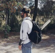
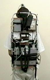
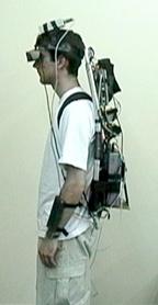
A simple ruck sack was used to carry all the components on the user’s back, as shown in Figure A‑2. This ruck sack did not organise the components inside and so was difficult to work with. Some issues associated with this ruck sack design are:
· Components are placed arbitrarily into the sack
Equipment moves around due to non-rigid mounting
Cables and connectors break easily due to movement inside backpack
Not possible to get easy access to components or wires
A.1.1 Software
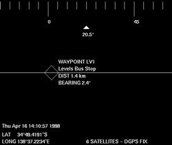
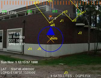
The software for this initial prototype was quite primitive and was not implemented with a software architecture. The application was a simple X11 program written for Linux that processed the compass and GPS inputs to draw a steering gadget onto the display. The optical overlay capability of the HMD was used to produce the final AR view of the world. The steering information was a diamond that overlaid the destination target along with bearing and distance values, as shown in Figure A‑3. This prototype was useful for discovering problems with the numerous components being integrated, and the knowledge gained was used for the development of future systems.
A.2 Tinmith-2 prototype (1998)
After the experience from Map-in-the-Hat a new system was designed from the ground up for the purpose of performing the mobile navigation task much more effectively. Instead of just providing simple navigation cues, this software was designed to support both 2D maps and 3D immersive wire frames with optical overlay [THOM99]. This version is implemented using a flexible software architecture [PIEK99b] designed to be extended for other tasks in the future. Later systems use this software architecture for the development of other applications. This version is named Tinmith-2, and there was no version one because this was reserved for the previous Map-in-the-Hat system. The name Tinmith was originally coined based on an abbreviation for “This Is Not Map In The Hat”, although is never referred to in this way.
A.2.1
Equipment
|
|

The equipment for this version was similar to the last, except the wearable computer and GPS were both replaced to improve reliability. The laptop had the added benefit of providing an LCD screen and keyboard to enable simple debugging while outdoors. The following equipment was added:
· Toshiba CDS320 Pentium-200 laptop (64 mb memory, 2 Gb hard drive, 800x600x16bpp 2D VGA with C&T 65555)
Garmin GPS 12XL 12 channel hand-held receiver with radio-based differential receiver (1 Hz updates at 5-10 metres accuracy)
A.2.2 Mounting
The carrying sack was replaced with a rigid frame (see Figure A‑4) that allowed much more stable attachment of the components to the backpack. This frame also permitted much greater access to the equipment and made debugging much easier for development. Some properties associated with this mounting are:
· Hiking frame with aluminium rails to attach components
Small amount of reasonably light equipment
Easy access to all equipment and wires, improving visibility and debugging
Objects held with packing tape and gravity assisted to hold in correct position
Laptop contained within a cardboard box strapped to hiking frame with packing tape
HMD controller not mountable and placed in the pocket of the user
Design not robust enough since the tape would gradually unattach from the frame
A.2.3
Software
|
|
|
Figure A‑5 2D top down map overlaid on physical world (using offline AR overlay)
Figure A‑6 2D top down map overlay with current location relative to nearby buildings |
This
application performed a similar navigation task as Map-in-the-Hat, but instead
used a top down view with a steering arrow (see Figure A‑5 and Figure A‑6)
to indicate the direction to walk in while at the same time showing a line
drawn map of the area with other waypoints [PIEK99b]. This arrow was much more
efficient to use since it was not limited to the field of view of the HMD; the
previous steering diamond could not indicate to the user the orientation of an
object that was to the side of or behind the user. Using the forearm keyboard
the user may mark new waypoints and control the information displayed. An
immersive 3D wire frame display (see Figure A‑7) was also developed so
that models could be overlaid onto buildings, and this was used to visualise
simple extensions to buildings in the physical world [THOM99]. Since the video
hardware supported only 2D acceleration, wire frame rendering and optical
overlay was used to minimise load on the CPU. This software also contained an
internal architecture that allowed various software modules to perform
different tasks and then share data over an internal bus. By separating the
software into modules it can be easily distributed across multiple machines,
supporting distributed processing and monitoring by outside computers on a
network. This distribution capability was useful when there were not enough
serial ports on the Toshiba laptop, and the Phoenix-2 was used to provide an
extra RS-232 serial port processed by a software module and then sent to the
main laptop.
|
|
A.3 Tinmith-3 prototype (1999)
For the Tinmith-3 prototype the existing software was extended so that it was able to share information with other wearables and indoor computer systems. Using the DIS protocol [IEEE93], various software applications may render views of both physical and simulated entities, and provide situational awareness to wearable and fixed users [PIEK99c]. The backpack was reconstructed to use rigid mountings and straps instead of the fragile packing tape, greatly improving its reliability.
A.3.1 Equipment
The equipment for this prototype was the same as the previous Tinmith-2, except the Phoenix-2 wearable computer providing the extra serial port was removed. The following components were added:
· Quatech 4-port PCMCIA serial adaptor
Lucent WaveLAN PCMCIA wireless network card
A.3.2
Mounting
|
|
The previous backpack using packing tape was rebuilt to use a more permanent and fixed design that was much more reliable, and is shown in Figure A‑8. Some properties of this new fixed design are:
· Same hiking frame as previous
Wooden panels hold devices that cannot mount directly to the frame, fixed with screws and straps
Panels held using metal brackets allowing some limited rearrangements
Frame is an awkward curved shape to mount to
HMD controller not mountable and placed in the pocket of the user
Laptop cannot be opened and used since it is tightly strapped up
Much more rigid, safer, and reliable design
A.3.3 Software
The same
software architecture from Tinmith-2 was used, except various extensions were
added to capture data from DIS protocol-based simulation software and present
it to the display module, with tracking information broadcast back to other DIS
simulation software. Figure A‑9 depicts the layout of all the modules in
the system, with the lsapdis and tracker modules providing the extra interfaces
for this support. Tinmith-2 contained the same modules and layout except for
these two extensions.
|
|
|
|

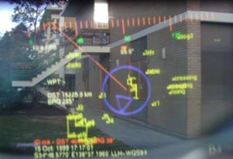
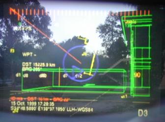
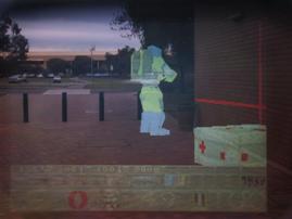
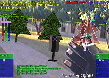
To demonstrate the system, the ModSAF tool (see Figure A‑10) is used to generate a set of simulated helicopters that fly across a virtual landscape according to a set of rules created by the simulation manager. The display for ModSAF can show the locations of entities it is simulating, as well as any entities generated by other computers, from a top down 2D control panel. The wearable user located outdoors (see Figure A‑11) generates DIS packets that are then displayed as another entity in ModSAF. For a VR style view, the MetaVR application is capable of rendering DIS entities onto a 3D landscape, with views such as Figure A‑12 showing an avatar of the wearable user observing a ModSAF simulated helicopter. On the AR HMD of the user, both of the previously discussed 2D top down and 3D immersive views may be used to display points and labels representing the entities simulated by ModSAF or generated by other wearable computers. The 2D view shown in Figure A‑13 is the wearable’s top down HMD view of the simulated entities in the previous figures.
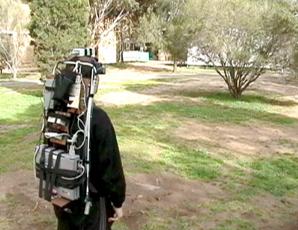
Figure A‑11 Wearable user in outdoor environment generates DIS packets
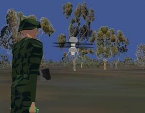
Figure A‑12 MetaVR view of avatar for wearable user and helicopter for ModSAF entity
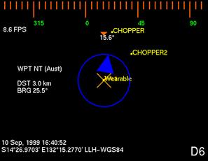
Figure A‑13 DIS entities overlaid in yellow on HMD with a top down view
A.4 Tinmith-4 and ARQuake prototype (1999)
The Tinmith-4 prototype was extended to develop two new applications. The first was an architectural visualisation application, where filled triangles can be rendered to the display to present to the user more realistic looking models. The game Quake was also modified to produce a new AR version named ARQuake [THOM00] [PIEK02d], using the Tinmith-4 software to provide position and orientation information about the user. These were the last applications developed using the current software architecture before it was replaced with a rewritten version.
A.4.1 Equipment
Same as the previous Tinmith-3 prototype
A.4.2 Mounting
Same as the previous Tinmith-3 prototype
A.4.3 Software
The
architectural visualisation application was developed by rewriting the previous
display module with a new 3D renderer, capable of drawing filled depth sorted
triangles instead of just simple wire frames. Numerous optimisations were
performed to make the rendering possible on the hardware available, and the
complexity of the models was limited to a few hundred polygons to keep
reasonable frame rates. Models were converted from AutoCAD DXF files and loaded
in, allowing architects to preview the models designed on desktop software with
outdoor AR systems, as shown in Figure A‑14.
|
|

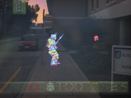
The
ARQuake application was developed using the GPL released Quake source code from
ID Software [IDSO01], and is a first person shoot-em up game so it has a view
point similar to a VR system. When operated on an optical overlay HMD, objects
in the game appear over the physical world, as shown in Figure A‑15.
Instead of using a keyboard or mouse to control the game, it was modified to
use the position and orientation sensors on the body as an input device. An
extra software module was written using the Tinmith architecture that generated
UDP packets for ARQuake based on the tracker values available. Using a custom
haptic feedback gun, the user may attack monsters using a highly intuitive
trigger input that most users are familiar with. Since the game does not
support individually aimed weapons, the gun is not tracked and the user aims
with their head.
|
|
A.5 Tinmith-evo5 prototype one (2001)
Although
the previous software architecture was quite powerful, it was optimised for the
navigation task and the use of older equipment. With the arrival of hardware
accelerated OpenGL and faster CPUs, I wanted to start doing research into
complex 3D modelling tasks involving input gloves, vision tracking, and live
video overlay. The goal was to produce an interactive modelling system that
used intuitive hand gestures to control the environment, with an artistic
impression shown in Figure A‑16. The capabilities desired were out of the
scope of the original software architecture and so a new one was designed to be
the platform for all my future AR application development. This prototype was
used to implement my first demonstrations of street furniture and infinite
planes modelling in AR [PIEK01b] [PIEK02c].
|
|

A.5.1 Equipment
For this update almost all of the equipment was replaced since the previous equipment was becoming quite outdated. The equipment added was as follows:
· Gateway Solo Pentium-II 450 laptop (64 mb memory, 6 Gb hard drive, 1024x768x24bpp OpenGL with ATI Rage Mach64)
CPIA chipset-based USB camera (352x288 frames at 5 Hz)
Custom designed pinch gloves with metallic pads and low power microcontroller interface
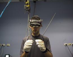
Glasstron PLM-700E 800x600 resolution HMD with opaque settings for video AR
LCD television rendering live video overlay previews for bystanders to observe during demonstrations
InterSense IS-300 hybrid orientation sensor (100+ Hz updates)
Trimble OEM Ag132 GPS with Omnistar satellite differential receiver (10 Hz updates at 50 cm accuracy)
12V lead acid batteries rated at 85 Wh
A.5.2 Mounting
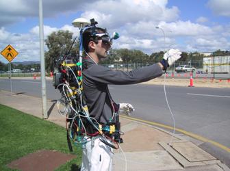
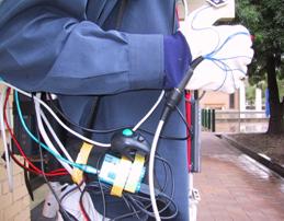
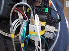
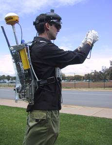
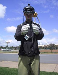
Similar mounting techniques as previous were used for the newer components, and due to the increased complexity of the design this backpack began to become unwieldy, as seen in Figure A‑17 and Figure A‑18. This was the last prototype to use the current backpack before the switch to the new Tinmith-Endeavour design. Some properties of the current design are:
· Component count larger due to increased functionality (TV output, cameras, gloves)
Cabling complexity increased due to extra equipment
Connectors fitted to waist holders for attaching devices while mobile
Not all devices fit the wooden panels and curvature of backpack frame
Difficult to add extra devices without moving all existing equipment around
Sony Glasstron was still not mounted, held with
a strap around the neck
|
|
|
Figure A‑17 Side view of original Tinmith-evo5 backpack, with cabling problems
Figure A‑18 Close up view of messy cable bundles and miscellaneous input devices |
A.5.3 Software
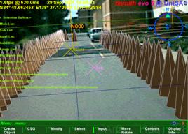
This
version uses a completely rewritten set of software designed to perform the
modelling tasks envisaged [PIEK01c] [PIEK02a] [PIEK03f]. The implementation was
described previously in Chapter 6, and is written in C++ and uses a much more
efficient model for processing data. Using an object-oriented approach, each
object contains data that can be listened on for changes by other objects in
the system. Since all the components of the application are written using this
software architecture, everything is tightly integrated and consistent. A user
interface based on cursors mapped to the user’s thumbs as well as a menu system
was implemented to support complex modelling tasks such as CSG and 3D
manipulation. The modelling tasks implemented were simple versions of the
infinite planes and street furniture techniques described previously. This
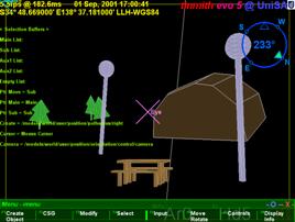
first prototype (with video overlay AR output shown in Figure A‑19) was
mostly used for experiments in testing out initial modelling techniques and
gathering information for the development of later improved versions.
|
|
A.6 Tinmith-VR prototype (2001)
As part of informal user experiments described in Chapter 5, I wanted to test the usefulness of the user interface in an indoor VR environment [PIEK02b] [PIEK02e]. Since the interface is relatively generic it may be used in VR systems with only slight tracker changes. The hardware used was similar to typical VR systems, with a Polhemus magnetic tracker and opaque HMD used indoors, as shown in Figure A‑20.
A.6.1 Equipment
This system did not use a backpack computer and instead used indoor-based hardware to render to the VR display. The components used were as follows:
· Dell Inspiron 8100 laptop with Pentium-III 1.2 Ghz (512 mb memory, 40 Gb hard drive, 1600x1400x24bpp OpenGL with NVIDIA GeForce2Go)
Polhemus magnetic tracker with 3 sensors
Daeyang Cyvisor 800x600 resolution opaque HMD
Power supplied from 240 volt mains supply
Custom designed pinch gloves with metallic pads and low power microcontroller interface (no vision tracking)
A.6.2 Mounting
Since the equipment was used indoors and the user has a limited working range, everything was mounted to various parts of the room. Some properties of this mounting are as follows:
· One Polhemus magnetic sensor was mounted on the HMD to track head motion
Two Polhemus magnetic sensors were mounted onto the gloves of the user, replacing the vision tracking system
User is tethered to the system via a cable bundle attached to the ceiling
Reliable and easy to configure since the
environment is fixed
|
|
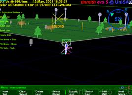
A.6.3 Software
The same modelling software previously described was modified to produce a VR version for use indoors, with a small example world shown in Figure A‑20. The video overlay was disabled, software reconfigured to use the Polhemus trackers, and extra features added to support the VR nature of the system. The same interface involving a cursor and menus was used to control the application, and users experienced with the outdoor system could use exactly the same interaction techniques to control the indoor system.
A.7 Tinmith-evo5 prototype two with Tinmith-Endeavour (2002)
For this
prototype, all of the lessons learned from previous versions were used to
redesign both the hardware and the user interface techniques. Although using
similar equipment to the previous prototype, a new backpack frame was designed
with DSTO for the specific purpose of being used for outdoor AR. The user
interface was redesigned and simplified to make modelling tasks for the user
easier, and a number of new construction at a distance techniques were added to
supplement the previous techniques. Many of the techniques discussed in this
dissertation are implemented in this prototype.
|
|
A.7.1 Equipment
Along with the new backpack design, a newer and much more powerful laptop was introduced that is capable of rendering live video overlay texture maps for AR at interactive frame rates. By using newer and higher resolution 1394 Firewire cameras, the quality of the video is improved dramatically from previous prototypes and produces much more compelling demonstrations outdoors. The new components used are as follows:
· Dell Inspiron 8100 laptop with Pentium-III 1.2 Ghz (512 mb memory, 40 Gb hard drive, 1600x1400x24bpp OpenGL with NVIDIA GeForce2Go)
Point Grey Research Firefly 1394 camera (640x480 frames at 15 Hz)
Trimble Ag132 GPS with Omnistar or radio differential receiver (10 Hz updates at 50 cm accuracy)
Custom designed pinch gloves with wire wound pads and low power microcontroller interface
A.7.2 Mounting
This prototype introduced the new backpack design from DSTO [PIEK02h], which was discussed previously in Chapter 7 and shown in Figure A‑21. Due to the flexible design of the backpack, components can be mounted in a number of configurations and easily changed. The following features are available with this backpack design:
· Using Velcro attachments, components can be easily rearranged
Cabled fixed internally with cable ties to prevent movement
Hinged design allows laptop to be used on a horizontal surface while outdoors
Laptop screen held open to permit bystanders to see live AR video overlay
Connectors and switches mounted on shoulder straps for easy access
New helmet design to mount cameras and trackers onto HMD
A.7.3 Software
The
software architecture for this system is similar to the first Tinmith-evo5
prototype, except that improvements were made to improve the implementation of
internal objects, speed up performance, and extend the serialisation mechanism
to use it for distributed indoor/outdoor collaboration tasks. The user
interface was improved based on the informal user studies discussed in previous
chapters [PIEK03d], making it more intuitive and efficient to control the
system with. While the previous prototype only implemented a small number of
outdoor modelling techniques, this new version implements many of the
construction at a distance techniques described in this dissertation [PIEK01b]
[PIEK02g] [PIEK03c]. This version contains the most up to date demonstration of
the techniques in this dissertation.
|
|
A.8 ARQuake prototype two with Tinmith-Endeavour (2002)
The previous Tinmith-evo5 prototype two used for outdoor AR modelling tasks is also able to run the modified ARQuake game discussed previously. For this version, the software was updated to use the latest Tinmith-evo5 software architecture and configuration system, supporting the latest equipment with improved accuracy and performance. The main noticeable improvement was the use of the GLquake source code with OpenGL acceleration and a video-based AR overlay modification to greatly improve the quality of the output [PIEK03a].
A.8.1 Equipment
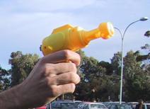
Same as
the previous Tinmith-evo5 prototype two, with an extra input device for
ARQuake. The haptic feedback gun was replaced with a much simpler USB-based
version that draws less power and looks more like a toy, as shown in Figure A‑23.
|
|
|
Figure A‑23 USB mouse embedded into a children’s bubble blowing toy
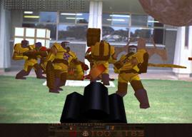
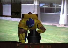
Figure A‑24 Monsters overlaid on the physical world with video overlay ARQuake |
A.8.2 Mounting
Same as the previous Tinmith-evo5 prototype two
A.8.3 Software
The ARQuake software described previously was rewritten to use the new Tinmith-evo5 software architecture, which is both more efficient and supports more types of tracking devices. The type of AR implemented was also changed from optical to video overlay, similar to the latest Tinmith-evo5 software. OpenGL stencil buffers were used to overlay a video texture onto the areas that were black in the original optical version. The final result is excellent image quality with vivid colours and sharp edges well suited for demonstrations, as shown in Figure A‑24.
This appendix has presented the history and evolving nature of the hardware and software developed as part of my research into outdoor AR. While the quality of the first AR systems was initially quite primitive with limited functionality, the latest AR systems are capable of performing complex 3D modelling tasks with displays that are much more compelling for the user.