4
“Applying computer technology is simply finding the right wrench to pound in the correct screw”
Anonymous
Chapter 1 - Construction at a distance
This chapter presents a series of new augmented reality user interaction techniques to support the capture and creation of 3D geometry of large outdoor structures. I have termed these techniques construction at a distance, based on the action at a distance term used by other researchers. My techniques address the problem of AR systems traditionally being consumers of information, rather than being used to create new content. By using information about the user’s physical presence along with hand and head gestures, AR systems may be used to capture and create the geometry of objects that are orders of magnitude larger than the user, with no prior information or assistance. While existing scanning techniques can only be used to capture existing physical objects, construction at a distance also allows the creation of models that exist only in the mind of the user. Using a single AR interface, users can enter geometry and verify its accuracy in real-time. Construction at a distance is a collection of 3D modelling techniques based on the concept of AR working planes, landmark alignment, CSG operations, and iterative refinement to form complex shapes. The following techniques are presented in this chapter: street furniture, bread crumbs, three types of infinite planes, CSG operations, projection carving, projection colouring, surface of revolution, and texture map capture. These techniques are demonstrated with a number of examples of real objects that have been modelled in the physical world, demonstrating the usefulness of the techniques.
1.1 Technique features
Current research in AR applications (as discussed previously in Chapter 2) has focused mainly on obtaining adequate tracking and registration, and then developing simple interfaces to present display information to the user. One important problem that has not been properly addressed is the authoring of the content that is displayed to the user. Since most AR systems are being used simply as a visualisation tool, the data is prepared offline with standard editing tools and then transferred to the AR system. Brooks states that one of the still unsolved problems in VR is the creation and capture of 3D geometry [BROO97], which is also relevant for AR models. To develop content for AR systems, I have developed a number of techniques I collectively termed construction at a distance. These techniques use the AR system itself to capture the 3D geometry of existing structures in the physical world, and create new 3D models for virtual objects that do not yet exist. Construction at a distance makes use of the AR working planes and landmark alignment techniques discussed previously in Chapter 3, and builds higher-level operations to perform the capture and creation of 3D models. This section describes some of the main features of my modelling techniques: supplementing existing physical capture techniques, working at a fixed scale in the environment, taking advantage of the previously defined AR working planes, performing iterative refinement of models, and the use of simplified operations to avoid the entry of vertices where possible.
1.1.1 Supplement physical capture limitations
The purpose of these techniques is not to replace existing object capture methods discussed in Chapter 2, which are highly accurate and can produce excellent results given the correct conditions. When working in unfavourable conditions, construction at a distance may be able to overcome these and capture a 3D model. Some examples of where my techniques are most useful are:
· I use a human operator that is capable of accurately estimating the geometry of planar shapes, even when partially occluded by other objects in the environment. When trees occlude the edges of a building, a human can estimate the layout based on the image information available and other knowledge.
The eye is a highly accurate input device capable of aligning along the walls of buildings within the limitations discussed previously. Accurate modelling is still possible when working from a distance and direct access to the object is not available.
Existing capture techniques have a fixed operation time no matter what the complexity of the scene is, whereas in my methods the human can judge the most appropriate level of detail. In many cases the user wants to create only simple shapes such as boxes to represent buildings, and so these techniques are ideal for quick operations.
Existing techniques require the object to already exist so it can be captured, whereas my methods allow the human to specify any geometry desired. This allows the creation of new shapes that do not physically exist and may be used to plan future construction work.
While the eye and brain are powerful capture devices, there are limitations introduced by the resolution and accuracy of the tracking devices used to record the inputs. For example, when using a GPS accurate to 50 centimetres the object size that can be modelled is in the order of metres (such as a car), while using a 1 millimetre magnetic tracker allows much smaller objects (such as a drink can). This research does not attempt to address problems with registration or accuracy of tracking devices, but instead works within the limitations of current technology to provide the best solutions that can be achieved.
1.1.2 Working at a fixed scale
In previously discussed VR research, a number of techniques have been developed for use in modelling applications. These applications traditionally provide tools to create and manipulate objects in a virtual world, and to fly around and perform scaling operations to handle a variety of object sizes. While techniques for action at a distance such as spot lights [LIAN93], selection apertures [FORS96], and image plane techniques [PIER97] have been developed, these only perform simple manipulations on existing objects and cannot be used to create new ones due to the lack of generating distance values. Techniques such as flying [ROBI92], Worlds in Miniature [STOA95], scaled world grab [MINE97a], and Voodoo Dolls [PIER99] can perform the creation of points by bringing the world within arm’s reach, but accuracy is affected by the scale. Due to their non-exact freehand input methods, all of these systems are also limited to conceptual modelling tasks and not precision modelling. CAD systems use snapping functions or exact numerical entry to ensure accurate inputs, but require an existing reference to snap to or non-intuitive command-based entry.
Although AR environments share some similar functionality with VR, AR is unique in that it requires registration of the physical and virtual worlds. Flying and scaling operations require the breaking of AR registration and so cannot be used. Scaled world representations force the user to divert their attention from the physical world to perform miniature operations within the hands. Existing VR techniques cannot create models of objects the size of skyscraper buildings without breaking the 1:1 relationship between the user and the virtual world. With construction at a distance techniques, the scale of the world is fixed and only the user’s head position controls the view. The virtual geometry is created using absolute world coordinates and is always registered and verifiable against the physical world in real-time. By using the physical presence of the user as an input device, the body can be directly used to quickly and intuitively control the view rather than relying on a separate input device.
1.1.3 Augmented reality working planes
As discussed previously, humans are much more capable of accurately estimating and specifying horizontal and vertical displacements compared to distances. By using the AR working planes and landmark alignment techniques formulated earlier, simple 2D input devices can be used to draw points in 3D. An AR working plane can be defined at any time from the body along the direction of view (maximising accuracy with landmark alignment) or relative to an existing object (maintaining the same accuracy as the source object), and the user can then move around to a different angle to draw against this surface. With AR working planes, the user is able to draw points that are at large distances and at locations that are not normally reachable, maintaining a 1:1 relationship between the virtual and physical worlds.
In order to draw against the working plane surface, a 2D input device must be used. This chapter is written without specifying any particular input device technology to demonstrate the generic nature of these techniques. Some of the examples in this chapter show a glove with fiducial marker-based tracking in use as the input device. A 2D cursor is overlaid on top of the fiducial marker and this is used to project points onto the AR working planes. Other input devices such as trackballs or joysticks can just as easily be used for this task. Chapter 5 will discuss further the implementation of the user interface, the input devices used, and how construction at a distance is implemented within applications.
1.1.4 Iterative model refinement
Construction at a distance relies on a set of fundamental operations that by themselves cannot generally model a physical world object. Combining a series of these fundamental operations by making iterative improvements can produce complex shapes however. As the modelling operation is taking place the user can see how well the virtual and physical objects compare, repeatedly making changes until the desired quality is gained. The previously discussed CSG techniques used by CAD systems also rely on this principle to produce highly complicated shapes that would otherwise be difficult to specify. The ability to instantly verify the quality of models against the physical world helps to reduce errors and decrease the total modelling time.
The process of iterative refinement for VR modelling is discussed by Brooks [BROO97], and he recommends that a breadth-first iterative refinement strategy is the most efficient. Each major object should be created using a simple representation at first, and then of each minor object of lesser importance. By refining the objects that require it, guided by the eye of the user, Brooks suggests that poor approximations will be immediately obvious and should be the first objects to correct. I have used these VR guidelines for my construction at a distance techniques, and take the refinement process one step further by using the unique ability of AR to compare virtual and physical worlds simultaneously. Instead of attempting to capture millions of polygons, construction at a distance focuses on simplicity and can be used to capture models at very simple detail levels if desired by the user. As mentioned in the background chapter, a laser scanner typically takes about one hour to capture a building from four different angles, producing a fixed number of millions of polygons with no control over detail. In comparison, if a simple model with only important features is required, the user can focus their efforts on these parts only and reduce the modelling time considerably. As an example, a building with four walls and a sloped roof was captured in the few minutes it takes to walk around and sight along each wall of the building.
1.1.5 Simplified
techniques
|
|
Some techniques have been developed previously for the interactive creation of data in virtual environments with no prior information. The previously discussed CDS system by Bowman can create vertices by projecting a virtual laser beam against the ground plane [BOWM96]. By connecting these points together and extruding the 2D outline upwards, full 3D solid objects can be created although they are limited in complexity by being constant across the height axis. The previously discussed work by Baillot et al. performed the creation of vertices located at the intersection of two virtual laser beams drawn from different locations [BAIL01]. After defining vertices these can then be connected together to form other shapes of arbitrary complexity, limited only by the time available to the user. Since these techniques both operate using vertex primitives that are then connected into edges, polygons, and objects, the complexity of this task increases as the number of facets on the object increases. Given a building object with n walls (along with a roof and a floor) there will be 2n vertices, 3n edges, and n+2 facets to process. Table 4‑1 shows some example objects with a varying number of faces, with linear growth for vertex and edge complexity. Rather than treating objects as collections of vertices, construction at a distance mainly operates using surfaces and solid objects, so an object with 10 facets can be modelled in 10 steps rather than as 20 vertices and 30 edges.
1.2 Direct object placement techniques
This section describes techniques involving the direct placement of objects within arm’s reach. While not being truly construction at a distance, these techniques may be used as inputs for other operations. These techniques are the simplest to understand for the user, although can be time consuming due to the physical movements required.
1.2.1 Street furniture
placement
|
|
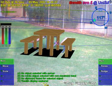
The
simplest way to perform modelling is to use prefabricated objects and place
them at the feet of the user as they stand in the environment. The object is
placed when commanded by the user, with its orientation specified relative to
the viewing direction of the user and always placed level to the ground plane.
I have termed this technique street furniture, as it can be used to place down
objects that commonly occur on the street, such as the table in Figure 4‑1.
This method works well when objects to create are known in advance, and the
user can avoid having to model the object each time. Due to the direct nature
of the technique, no abstractions are required for the user to understand since
physical movements are used to control the object placement. By instantiating
objects at the user’s feet, tracking of the hands can be completely avoided to
simplify the task further. While this is not construction at a distance
according to the definition, it is the most basic and simplest operation that
can be performed using a mobile outdoor AR computer. Later techniques described
in this chapter use direct placement for the creation of infinitely sized plane
surfaces in the environment. The main limitation of this technique is that the
user must be able to walk up to the location desired. When the object cannot be
reached, techniques that can perform true construction at a distance must be
used.
|
|
|
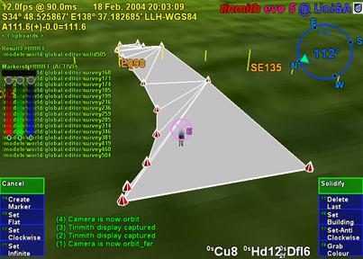
Figure 2‑2 VR view of bread crumbs markers defining a flat concave perimeter
Figure 2‑3 AR view showing registration of perimeter to a physical world grassy patch |
1.2.2 Bread crumb trails
Using the
previously defined street furniture technique to place down prefabricated
shapes is useful but limited to objects created in advance. For large objects
such as rivers, lakes, trails, roads, and other ground features I have
developed a technique named bread crumbs. In many cases it is possible to walk
near the edges of these ground features, and so a direct system of marking out
their vertices is realisable. The bread crumbs technique is inspired by the
children’s fairytale Hansel and Gretel [GRIM22]. In this story, the children
are taken out into the forest by their parents in the hope they will not come
back home again. Hansel was carrying a loaf of bread however, and dropped small
crumbs of bread where they walked, enabling them to find their way back home
again. On the second occasion, the children found themselves unable to get home
because the birds in the forest ate up the trail.
|
|
With a mobile AR system, less edible and more reliable virtual markers can be placed down on the ground to simulate bread crumbs. The user walks along the perimeter of the object they wish to model and manually specifies markers to place at points of interest under the feet, as shown in Figure 4‑2. This is the same as marking waypoints when using a hand-held GPS while walking. When the user fully walks around the object, a closed perimeter is automatically formed and converted into polygons, as in Figure 4‑3. While the initial perimeter defined is a thin polygon, it can be infinitely extruded up to define a solid building outline, or infinitely extruded down to approximate the bottom of a lake or river. The resulting extruded object is unbounded in the vertical direction as shown in Figure 4‑4, and must be completed using other techniques described later.
The bread crumbs technique has been used to model roads, parking lots, grassy areas on campus, and other concave outline style shapes. Paths and navigation routes may also be defined using bread crumbs, except treated as a line segment instead of a solid polygon.
1.3 Body-relative plane techniques
This section describes a series of construction at a distance techniques based on the user’s physical presence in the environment. Using simple head-based pointing, the geometry of planes originating from the body can be specified, taking advantage of the user’s sense of proprioception. Using CSG techniques, these planes can be used to easily define solid building shapes out of arm’s reach. Since many buildings in the physical world can be modelled using planes, the process of modelling can be accelerated compared to the simplistic approach of creating each vertex and edge manually.
1.3.1 Orientation infinite
planes
|
|
Buildings in the physical world tend to approximate collections of angled walls in most cases. As described in Chapter 2, a solid convex cube can be formed with the specification of six planes arranged perpendicular to each other and a CSG intersection operator. Instead of specifying these planes numerically, the user can create these same planes in an AR environment by projecting them along the line of sight. By looking along the plane of a wall of a building and aligning the two ends (a very accurate method of positioning discussed previously) the user can project an infinite plane along this wall (in a similar way to AR working planes). Each plane defines a half space that when combined with a CSG intersect operation will form a finite solid shape.
Figure 4‑5 depicts a five-sided building and the location of the mobile AR user as they are sighting down each of the walls, showing the infinite volume being iteratively bound by the infinite planes. At the beginning of the operation, the AR system creates an (approximately) infinite solid volume that will be used for carving. When the user is aligned with a wall, they project an infinitely long vertical plane along the view direction into the world. This plane divides the previous infinite solid into two parts and the left or right portion (decided by the user) is carved away from the solid and removed. As the user sights along each wall, the solid will be reduced down to an object that is no longer infinite in the X and Y axes. At completion, a floor is automatically created at ground level, and the roof is left unbounded for carving using other techniques, since it is impractical to sight along the roof of a very tall building. The final 3D shape is stored using absolute world coordinates and reflects the geometry of the physical building.
With this technique, the object can be carved away iteratively and the user receives real-time feedback of the infinite volume being bounded, allowing immediate undo in case of a mistake. Compared to the direct methods described previously, this plane-based technique allows the capture of buildings from a distance without having to actually stand next to or on top of the building. Since the user is in direct control of the modelling process, the positions of occluded surfaces can be estimated using their knowledge of the environment. These features are useful because many existing physical capture methods require a full view of the object, GPS trackers do not work well near large buildings, and standing on top of a building may not be possible or too dangerous. This technique is also much more efficient than vertex and edge specification since each wall is handled with a single primitive that is easy to create accurately. A limitation of this technique is that using only planes and a CSG intersection to define objects restricts usage to convex buildings with no indentations, and this will be addressed further at the end of this section.
1.3.2 Position infinite planes
Another
limitation of the orientation infinite planes technique is the dependence on an
orientation sensing device for the head. While GPS units may have reliable
accuracies in the order of 2 cm, orientation sensors vary in accuracy due to
problems with interference and limitations of the technology. These variations
affect the placement of planes in the environment and as the distance from the
user increases, angular errors cause increasing positional errors. The last
section of this chapter will further discuss the accuracy of these techniques
in more detail, but using techniques that can avoid the use of orientation
sensing should be able to produce much more accurate results.
|
|
In order
to take advantage of the stability of position tracking, the orientation
infinite planes technique described earlier can be modified to use two or more
position points to specify orientation, making it invariant to errors in
orientation tracking devices. Using the same landmark alignment concept
discussed previously, the user can accurately sight along a wall and mark a
position. To indicate direction, the user walks closer while maintaining their
alignment and marks a second point. These two points can then be used to
project an infinite carving plane, with Figure 4‑6 depicting the position
markers and planes used to form a complete building shape. By increasing the
spacing of the marker points or using a line of best fit amongst multiple
points, the accuracy of this technique can be further improved.
|
|
|
Figure 2‑7 Relationship between GPS accuracy and required distance to achieve better than 1 degree of orientation error for two different GPS types |
To measure the accuracy of this technique, Figure 4‑7 depicts how the angular error is affected by the positional error in the GPS and the distance between the two marker points. To make this technique useful it must have an accuracy that is better than is available using traditional orientation sensors. Assuming a maximum error of 1 degree, Figure 4‑7 contains the calculations to find the distance required between markers for 50 cm and 2 cm accurate GPS units. Using the RTK example, if 1.1 metres is required for less than 1 degree error then 10 or more metres will produce orders of magnitude better results than previously possible. For a 50 cm GPS these results are not so promising since the marker distance required of 29 metres is quite large - the user will have to choose between the errors introduced by the GPS or those from the orientation sensor.
1.3.3 Fixed infinite
planes
|
|
This technique is similar to the position infinite planes technique in that it is invariant to orientation sensing errors. The previous technique required the user to specify the orientation for each plane by using two points, but if the angles at each corner are known to be equal then only one orientation is needed and the others can be calculated automatically. The user creates the first plane using the same method described previously, but for each additional plane only one position marker is recorded. Based on the number of positions marked, the system knows the number of walls to create and calculates the orientation for each position point based on the first plane. This technique uses nearly half the number of points and yet produces the same accuracy if the first plane is properly placed and the building meets the required properties. Figure 4‑8 depicts the markers created by the user and how they are used to project planes through the environment to form a solid shape.
1.3.4 CSG operations
Many
objects in the world are not the same shape as simple boxes, cylinders,
spheres, and cones. While it may seem that many objects are too complicated to
model, they may usually be described in terms of combinations of other objects.
For example, the process of defining a cube with a hole using vertices is time
consuming, but can be easily specified with a CSG operation. As discussed in
the background chapter, CSG is a technique commonly used by CAD systems,
supporting Boolean set operations such as inversion, union, intersection, and
subtraction [REQU80]. The manufacture of objects in the physical world is also
performed in a similar manner - to produce the previous example a drill is used
to bore out a hole in a solid cube.
|
|
To demonstrate CSG operations outdoors, Figure 4‑9 depicts an example where a user is applying the CSG difference operator to subtract cubes from a building shape. This could be used when the user needs to carve out indented windows. The first example shows a cube placed at a distance (1a), and then dragged sideways until it enters the building shape (2a). The second example shows a cube attached to a working plane (1b) and then pushed (2b) into the surface of the building (similar to a cookie cutter), requiring close access to the building. As the cube is being positioned by the user, the CSG difference operator is interactively calculated and displayed to the user.
The
infinite planes examples previously described have only dealt with convex
shapes, limiting the types of buildings that can be modelled. A convex shape
can be simply described as one that appears to have the same shape when a sheet
of rubber is stretched over its surface, such as the trapezoid in Figure 4‑10.
A concave shape is more complex and contains holes or other indentations that
will not be visible when a sheet of rubber is stretched over. Concave buildings
similar to the T, L, and O shapes in Figure 4‑10 cannot be modelled
directly using a single set of infinite planes because planes from one part of
the object will exclude other parts. Concave objects can be created using other
convex objects as inputs however, such as with the subtraction of one box from
another depicted in Figure 4‑11. The two boxes can be individually
created using infinite planes, and then combined using a CSG difference
operator to produce a concave object. When combined with CSG techniques,
infinite planes become more useful with the ability to also model concave
objects.
|
|
|
Figure 2‑10 Convex trapezoid and concave T, L, and O-shaped objects
Figure 2‑11 Concave object created using CSG difference of two convex boxes |
1.4 AR working planes techniques
This section describes a series of construction at a distance techniques based on AR working planes. The previous techniques are capable of placing prefabricated objects and capturing bounding boxes for large objects, but detailed modelling is not provided. Using AR working planes and a 2D input glove (as used in these examples), the user can specify much more intricate details to create realistic 3D models.
1.4.1 Projection carving
The
projection carving technique modifies existing objects by projecting points
against surfaces and then cutting away extrusions to produce new highly concave
shapes. This technique provides the ability to construct features such as
zig-zag roofs and holes that are difficult or impossible to model using
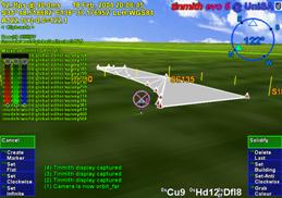
previously described techniques. Figure 4‑12 depicts an example of how
this technique can be used to carve two peaked roofs onto a building model.
These building models may have been created using infinite planes and
projection carving can be used to restrict the infinite roof to a finite
volume. The AR working plane is created relative to a polygon that has been
selected by the user. The object that contains the polygon is then used as the
input for the upcoming carving operation. The user then creates vertices along
the surface of the AR working plane and these are connected together to form a
2D concave outline. This outline is then extruded along the surface normal of
the working plane and used as an input tool for a CSG difference carving
operation.
|
|
|
Figure 2‑12 AR working planes are used to specify vertices and are projected along the surface normal for carving the object’s roof |
The projection is performed using orthogonal extrusion from the AR working plane, and is position invariant so points can be entered from any location in front of the polygon. This enables the user to cut a flat roof on a 100 metre high building while standing at ground level and looking up. If the cursor was directly used to carve the object directly like a laser beam, the system would produce pyramid-shaped extrusions. For some buildings, the user may only desire to create a flat roof or a single slope, and by creating only one point the system will create a horizontal cutting plane, and with two points a diagonal cutting plane is created. More than two points implies the user wishes to cut with an outline and so it must be fully specified as in Figure 4‑12. The CSG operation can be switched from difference to intersect if desired, with the effect being that the user can cut holes or split an object into separate parts instead of carving the outside. Used in this form, orthogonal extrusion is limited to carving operations that can be seen in a silhouette representation – other features such as indentations that are not visible from the side can not be captured with this technique. Some of these limitations can be overcome by limiting the depth of the extrusion used for carving. By using a small fixed value or controlling it by moving the body forward or backward, the extrusion can be controlled by the user and used for features such as windows or doors.
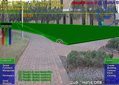
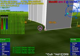
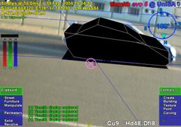
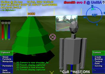
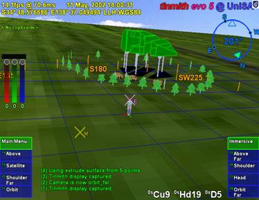
This technique is first demonstrated with a simple example of modelling a building with a sloped roof such as in Figure 4‑13. The user first captures the overall geometry of the building using orientation infinite planes with an unbounded roof. To carve the roof, the user positions their body somewhere in front of the building so that the entire slope is easily visible. The user then indicates with the cursor the first vertex defining the roof on the left, then the peak of the roof, and then the right side of the roof, as shown in Figure 4‑14. To complete the selection, the user must enter vertices around the overall building to indicate that the rest of the object should be kept. The selection region is then used to define a carving tool that removes all objects outside the region, to produce the final shapes shown in Figure 4‑13 and Figure 4‑15.
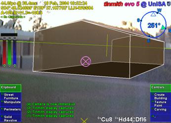
Figure 2‑13 AR view of infinite planes building created with sloped roof
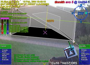
Figure 2‑14 AR view of infinite planes building being interactively carved with a roof
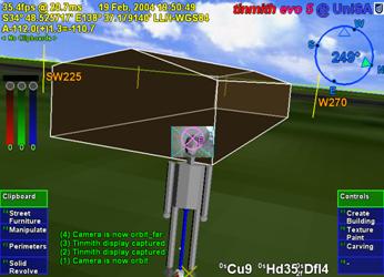
Figure 2‑15 VR view of building with sloped roof, showing overall geometry
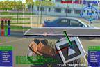
A second
example demonstrating this technique is a small automobile being modelled
outdoors in Figure 4‑16. Firstly, a prefabricated box is created and
scaled to approximate the overall dimensions of the car. The user next views
the car from the side and intersects points against the box surface to define
the silhouette. Figure 4‑16 shows the markers being placed on the box,
and Figure 4‑17 shows the final solid shape of the car approximately
matching the physical world. The object can then be carved along any other
polygons to further refine the model until it suits the user’s requirements.
 2
2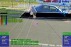 3
3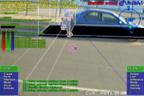 4
4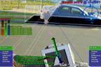
 6
6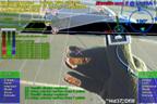 7
7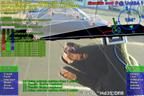 8
8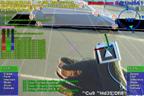
1.4.2 Projection colouring
Once a
building has been created, the user may desire to place windows, doors, and
other extra details onto the model. While it may be possible to draw these
details onto a texture map (which cannot be zoomed arbitrarily), or to place
extra polygons outside the building to represent these (covering the original
building), the building model itself remains untouched. If these new polygons
are removed or manipulated, the original solid object remains since the changes
are only superficial. A more desirable scenario is that polygons of a different
colour are actually cut into the subdivided surface of an object, so that if
they are deleted it is possible to see features inside the object that were
previously concealed. I have named this technique projection colouring and its
operation is depicted in Figure 4‑18. Using the same steps as projection
carving, vertices are projected against an AR working plane created relative to
the surface and then connected into an outline. Instead of carving away the
outline, the surface is subdivided and the colour of the outlined polygon is
modified. The newly coloured polygons may then be deleted or manipulated freely
by the user if desired. The window and door in Figure 4‑18 have been cut
into the surface using this technique, with the door then openable using a
rotation.
|
|
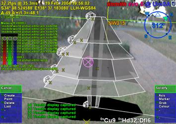
1.4.3 Surface of
revolution
|
|
When
working outdoors and modelling natural features such as trees and artificial
features such as fountains, box-shaped objects are usually poor approximations
to use. In an attempt to model these objects, I have used surface of revolution
techniques (as used in many desktop CAD systems) to capture geometry that is
rotated about an axis. The user starts by creating an AR working plane in the
environment, with the most intuitive way being to sight toward the central
trunk of the tree and project the AR working plane along the view direction. The
user then projects vertices onto the AR working plane, defining one half of the
outline of the object. After specifying the vertices along the axis of
rotation, the system generates a solid object by rotating the outline around
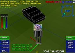
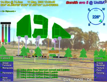
the axis, as depicted in Figure 4‑19. Figure 4‑20 shows an example
where the vertices of a tree have been specified with a preview shape
generated, with Figure 4‑21 showing the final shape in the environment.
This technique generates good results when modelling natural objects such as
pine trees that are highly symmetrical about the trunk. For trees that grow
with deformities and other non-symmetrical features this technique may not
generate suitable approximations. To improve the approximation, previously
described carving techniques may be applied to refine the model until the user
is satisfied with the object.
|
|
|
Figure 2‑20 AR view of surface of revolution tree with markers on AR working plane
Figure 2‑21 VR view of final surface of revolution tree as a solid shape |
1.4.4 Texture map capture
When
implementing live AR video overlay, the mobile computer includes a video camera
that may also be used to supply textures for polygons. By using the same
tracking devices that are already required for AR, the system can automatically
match up images from the camera to polygons in the scene. Captured models are
normally only presented using a single colour and texture maps increase the
realism for users without having to add extra polygons for detail. This texture
map capturing technique is an alternative to the previously described
projection colouring technique when only superficial details are required. To
perform texture map capture, the user stands at a location where the texture
for an object’s polygon is clearly visible to the camera. The user selects the
polygon to activate capture mode and the system projects the polygon vertices
onto the AR video overlay to map the still image as a texture. The user repeats
this operation for each polygon until the object is completely textured. An
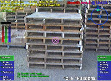
example is shown in Figure 4‑22, where a stack of pallets is modelled
using a 1 metre box and then textures are captured for the polygons. The final
resulting model is shown in Figure 4‑23.
|
|
|
Figure 2‑22 Outdoor stack of pallets approximating a box, before modelling
Figure 2‑23 VR view of final model with captured geometry and mapped textures |
The best results for this technique are obtained when the object is fully visible and fills as much of the HMD as possible, as well as being perpendicular to the user’s viewing direction. Since OpenGL only supports linear texture mapping, if the angle to the polygon is large (such as the roof of the box in Figure 4‑22 and Figure 4‑23), the texture will be highly distorted since a non-linear mapping is required. Although techniques for capturing textures of 3D models have been described previously, this has not been performed in a mobile outdoor AR environment. Previously discussed work by Debevec et al. implemented the capture of 3D models from photographs and extracted textures for each facet [DEBE96]. Lee et al. also implemented the capture of textures in AR but with surfaces being modelled within arm’s reach using a wand, with the system automatically capturing textures when video frames were deemed suitable [LEE01]. The video stream used with mobile AR suffers from problems with motion blur and tracker registration, and having the user choose the moment to capture the texture generates the highest quality output.
1.5 Integrated example
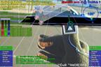
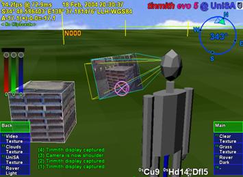
While a number of techniques can perform the modelling of simple and useful shapes, the true power of construction at a distance is expressed when used in combinations. This integrated example is designed to highlight all of the features of the described modelling techniques with the construction of an abstract building in an outdoor environment. The user walks outside to an empty piece of land and creates a landscape that they would like to preview and perhaps construct in the future. As an added feature, this model may be viewed on an indoor workstation either in real-time during construction or at a later time. Some other similar applications are for creative purposes such as an abstract art or landscape gardening design tool.
Figure 4‑24 and Figure 4‑25 show different views of this example at the end of the construction process. The first step is to create the perimeter of the building shape using the bread crumbs technique - the user walks around the building site and places down markers at the desired ground locations, forming a flat outline. Next, the outline is extruded upwards into a solid 3D shape. Using projection carving, the user cuts a main roof to make the object finite and then carves a slope using various control points. After the overall roof structure is created, the object is lifted into the air. At this point, the supporting columns, trees, tables, and avatar people are created using street furniture placement of prefabricated models at the desired locations. The building is then lowered by visual inspection onto the supporting columns. Next, the user performs further carving and a large hole is created through the centre of the building. Projection carving is then used to cut out two large sections of the building, causing it to exist as three unattached solid shapes most visible in Figure 4‑24. After around 10 minutes for this example, the desired model is complete and the user can now move around the environment to preview it from different view points.
1.6
Operational performance
|
|
|
Figure 2‑24 AR view of final abstract model, including street furniture items
Figure 2‑25 VR view of final abstract model, including street furniture items |
The construction at a distance techniques rely on the position and orientation sensors for all tracking, and so increasing the accuracy of these devices will produce improved results and affect the minimum model size that can be properly captured. Errors from each sensor have different effects on the captured models since one is measured as a distance and the other as an angle. When rendering the AR display, results are also affected not only by the errors in the current tracker data, but also those from the capture process. Tracking devices affect the overall operation of the system and how it can be deployed in the physical world.
The position sensor used in these examples is a Trimble Ag132 GPS, with an accuracy of approximately 50 centimetres and working reliably amongst small buildings and light tree cover. To ensure the most accurate positioning possible, an indicator on the HMD shows the quality of the GPS signal to the user. For orientation, an InterSense IS-300 hybrid magnetic and inertial sensor is used, although the tracking is unreliable when there are magnetic distortions present in the environment or when the user is moving quickly and disturbing the sensor. Since the accuracy of the IS-300 may vary unpredictably, this is the most critical component in terms of reliability and accuracy.
When modelling a new object, the accuracy of projection-based techniques is dependant on the user’s current location and the direction they are looking. For the highest accuracy, it is desirable to be as close to the object as possible, minimising the distance the projection can stray from the desired direction caused by angular errors in the orientation sensor. When viewing an existing virtual object, the registration errors with the physical world caused by the GPS will be the most accurate when viewed from a distance due to perspective, while standing very close to an object will cause these errors to be more noticeable. For registration errors caused by the IS-300, these remain constant on the display at all distances due to their angular nature.
While GPS is fast and reliable (with accuracies of RTK GPS units at 2 cm in ideal conditions), improvements in orientation sensing technology are required to make the construction at a distance techniques more accurate. While the IS-300 is one of the best mid-range priced trackers on the market, it is still not completely adequate for modelling outdoors. Due to its use of magnetic sensors, distortion caused by sources of magnetic interference such as the backpack, underground pipes, and street lamps affect the accuracy of the tracking. To correct for this, the backpack contains a touch pad mouse attached to the user’s chest to apply a correction offset. The touchpad allows the user to fine tune the calibration while moving outdoors through varying magnetic fields. I am currently investigating methods of automating this calibration, with methods such as optical natural feature tracking holding promise, but these are still current research problems.
1.7 Summary
This chapter has presented my novel construction at a distance techniques, designed to support the capture and creation of 3D models in outdoor environments using AR. Construction at a distance takes advantage of the presence of the user’s body, AR working planes, landmark alignment, CSG operations, and iterative refinement to perform modelling tasks with mobile AR systems. The techniques described in this chapter include street furniture, bread crumbs, three types of infinite planes, CSG operations, projection carving, projection colouring, surface of revolution, and texture map capture. When used in an AR environment, users can capture the geometry of objects that are orders of magnitude larger than themselves without breaking AR registration or having to touch the object directly. These modelling techniques are intuitive and support iterative refinement for detail in areas that require it, with AR providing real-time feedback to the user. While existing techniques are available for the capture of physical world objects, these still have limitations and also cannot be used to create models that do not physically exist. The construction at a distance techniques were field tested using a number of examples to show how they may be applied to real world problems. By discussing insights gained from these examples I have identified areas for improvement that currently cause accuracy problems.