6
“A fax machine is just a waffle iron with a phone attached”
Abraham Simpson
Chapter 1 - Software architecture
This chapter presents a new software architecture that I have developed, named Tinmith-evo5, for the development of the applications described in this dissertation. In order to implement a modelling application with AR working planes, construction at a distance, and user interface, a complex underlying infrastructure is required to simplify the development. Currently there are a limited number of existing toolkits for the development of 3D virtual environment applications, but each is optimised for a particular feature set different from the ones that I require. Tinmith-evo5 is designed for the development of mobile AR and other interactive 3D applications on portable platforms with limited resources. The architecture is implemented in C++ with an object-oriented data flow design, an object store based on the Unix file system model, and also uses other ideas from existing previous work. The Tinmith-evo5 software architecture addresses the following problems currently affecting mobile AR and similar environments:
· Hardware changes rapidly over time, and so should be abstracted to allow portability across different environments without changing the source code.
Mobile AR is limited by portability constraints and choices must be made between large and powerful or small and less capable equipment. Software for outdoor use must be efficiently designed and be able to run on mobile hardware that may be a number of generations behind current state of the art indoor computers.
3D graphics systems traditionally operate using a flat Earth model and do not readily deal with large areas of the planet that can be roamed with a mobile AR system. Being able to handle coordinates that span a wide range of scales, from millimetre-level tracking of the hands to moving over hundreds of kilometres of land is required.
User interfaces for mobile AR are quite primitive and there is limited toolkit support for developing applications. This problem is difficult to solve and current development in this area is quite immature.
This chapter begins with a design overview, followed by a summary of previous work describing existing systems and their features. The design of the architecture is then described, including concepts such as data flow and object distribution. The object storage system forms a core part of the architecture and is described in the following section. The next section describes the more interesting aspects of the implementation of the software. The abstraction of trackers and sensors with four different representations is then described. The usefulness of this software architecture is demonstrated with the applications developed for this dissertation and a number of extra demonstrations presented at the end of this chapter.
1.1 Design overview
Three dimensional environments are a challenging area to develop applications for since hardware devices are constantly evolving and non-standardised, there are a number of approaches to user interface design, and each application has different requirements. In 2D desktop environments, similar problems are better understood and high-level software toolkits are available so developers can focus on writing applications rather than implementation details. With 3D environments being newer and less understood, most available software toolkits are simple and low level, such as hardware abstraction layers. Shaw et al. explain how the development of high-level software is not possible until there is a stable base of low-level toolkits to support them [SHAW93]. Beyond simple abstractions however, there are only a few software systems that attempt to address higher-level problems and each is designed for supporting particular types of applications. This chapter develops a high-level architecture that is demonstrated with a mobile AR modelling application but may be also useful in other application domains.
The first
main concept used in the software architecture is that of data flow. Figure 6‑1
depicts this data flow from an overall perspective, with sensor data arriving
into the AR system, being processed by specific application code and
configurations, and then rendered to the HMD of the user. The data flow model
is supported by the use of objects to perform specific actions such as
processing tracker data, combining results, and rendering 3D graphics. Objects
allow problems to be broken down into simple tasks to simplify software
development. Objects are connected together into a directed graph, and as new
values enter the system, the values are processed through the graph as a flow
of data, adjusting the current state and eventually rendering to the HMD. These
objects can be distributed across multiple processes or computers in units
named execution containers, with the data flow occurring over a network when
required.
|
|
|
Figure 2‑1 Overall architecture showing sensors being processed using libraries and application components, and then rendered to the user’s HMD |
Research toolkits are designed using many different methodologies and are difficult to use together because of conflicting requirements. In the future these may become standardised but for now I avoid trying to make immature and opposing toolkits work directly together so that I can perform research into new ways of developing software. All the components of the architecture are developed from the ground up using a common methodology, with abstractions to hide away any differences from external libraries that are required. The goal is to not to treat the application as a combination of scene graph, tracking library, and shared memory, but instead as a single entity with blurred boundaries.
As part of the integrated component design methodology, the entire system has been structured around the model of a memory-based file system. Instead of using global variables to reference the many objects available in the system, an object storage system based on Unix file system semantics provides a logical interface that is easy to understand. All objects that process data in the system are stored in this object repository, making them accessible to other objects in the system through discovery at run time. The ability to perform distribution across multiple computers is added as an extra component using object data flow, and is not an internal part of the architecture that imposes a constant performance penalty whether in use or not.
The most important goal with the design of this software architecture is performance. Due to limitations in wearable computer hardware, it is important that as much work as possible be extracted out of the resources available. The C++ language and optimising compilers are used for all development, supporting both low-level code and high-level features such as object-oriented programming. The renderer that forms a core component of most applications is implemented using OpenGL and provides high performance graphics support when 3D acceleration hardware is present in the system. The software has been used on a number of small and relatively slow computers and is capable of running adequately in most cases, the exception being the rendering of large 3D scenes.
1.2 Previous work
There has been a wide range of previous work in the area of software toolkits for the implementation of VE applications, although there is no complete solution and is still an active research area. Shaw et al. describe how developing high-level tools requires a good understanding of the types of interactions, as well as low-level toolkits to provide necessary support. To support this statement, Shaw et al. explain how high-level tools for 2D user interfaces did not appear until researchers gained sufficient experience developing interfaces with this style. These high-level tools also did not exist until other more low-level toolkits were created to provide the necessary services. Currently the VE area is still quite immature when compared to 2D environments, and so more understanding is required to implement a usable toolkit.
This section discusses a number of low and high-level toolkits that have been developed to help implement VE applications efficiently. There are a number of areas that need to be addressed, such as data distribution, rendering, user interaction, tracker abstractions, and rapid prototyping. There is no single toolkit that solves all problems however, as tradeoffs must be made to support one feature at the expense of another. Tinmith-evo5 uses many of the ideas developed in these toolkits and applies them to the problems that need to be solved for mobile outdoor AR. Software architectures for areas such as wearable context awareness or other high-level information sharing are not described since they do not support 3D user interfaces.
1.2.1 Hardware abstraction libraries
Virtual environments typically require the use of tracking devices that measure three or more degrees of freedom. Tracker abstraction layers are implemented to hide away various differences in hardware and provide a common model so that the application only needs to be written once for many devices. Similar abstractions are commonly used for 2D desktop input devices such as mice and keyboards. Researchers such as Shaw et al. and Taylor et al. identified the need to have these abstractions in 3D environments and implemented software toolkits such as the MR Toolkit [SHAW93] and VRPN [TAYL01]. Shaw et al. saw the MR Toolkit as being an important low-level component for future development of higher-level user interface libraries. With many VE systems of the time being implemented using multiple computers, both MR Toolkit and VRPN are designed to support the transmission of tracker updates via packets on a network. Trackers can be moved to different machines or replaced with different devices without requiring any changes to the source code of the applications that use them.
Other toolkits have also been developed, increasing the levels of abstraction beyond just input devices: Hubbold et al. developed the MAVERICK system [HUBB99], Bierbaum et al. developed the VrJuggler libraries [BIER01] [BIER98], and Kelso et al. developed the DIVERSE libraries [KELS02]. Each of these systems provides an inner kernel that connects together various components such as input abstractions for trackers, support code for processing data, and output abstractions to various rendering systems such as OpenGL, IRIS Performer, and Open Inventor. These systems all provide similar functionality to those discussed previously, providing network transport for tracker device updates and the ability to modify configurations either at startup or at run time without modifying source code.
Another recent tracker abstraction is OpenTracker by Reitmayr and Schmalstieg [REIT01b]. It implements abstractions similar to those discussed previously, but in the form of a filter graph for arbitrary processing. Three different types of object nodes are provided: source nodes to read values from trackers, filter nodes to take source values and perform operations such as smoothing and conversions, and sink nodes to take the results and output them to other parts of the system. Using XML configuration files, the user can define complex filter graphs without requiring source code to be modified.
Other more high-level libraries (such as Coterie [MACI96], Division’s dVS [GRIM93], and the Sense8 World Toolkit [SENS03]) discussed later in this section also include abstractions similar to those previously mentioned.
1.2.2 Distributed entity systems
One current area of investigation is the implementation of distributed virtual environments. This involves simulating entities on machines and then viewing them on remote clients over a network. The main focus of this research is on the protocols rather than the toolkits, such as SIMNET by Calvin et al. [CALV93] and NPSNET by Zyda et al. [ZYDA92] that use protocols similar to DIS [IEEE93]. These protocols are not able to send full scene graphs or object databases, but instead only send position, orientation, and other simple data for each entity. The client viewer is responsible for supplying the models and performing the rendering, which is not defined by the protocol. By making these restrictions however, these systems are efficient and tend to scale up to large numbers of entities and computers.
Other systems such as the previously described BARS extend the distribution of data to wearable computers. Brown et al. describes the development of a data distribution mechanism for events to support collaboration between multiple users [BROW03]. Since the system only propagates events, complicated geometry and animation are not transmitted over the network and are assumed to be stored locally. The propagation of events may be used to convey objectives to mobile AR wearable users, communicate messages and reports, and update entity locations and attributes in a database.
A common problem with many distributed systems is that network data is decoded using fixed programs that can only handle protocols known in advance. For example, software that handles DIS protocol requires modifications if any of the enumerated values change meaning. These problems are addressed by Watsen and Zyda with the Bamboo system [WATS98a] [WATS98b]. Instead of having a single monolithic code base, Bamboo contains a small kernel that can perform the loading of other modules. When information arrives from the network that cannot be decoded, a request is sent for a decoder object. When the decoder object arrives, Bamboo loads it into memory so that the incoming packets can be processed. Bamboo uses a plug-in architecture to allow reconfiguring of software at run-time, and does not require modules to be stored locally. Other systems such as Octopus by Hartling et al. [HART01] also support distributed VE applications based on similar protocols to that used in Bamboo.
1.2.3 Software systems
There are a number of software systems that implement higher-level abstractions, using concepts previously described as a base for further development. Two early commercial toolkits are dVS by Grimsdale [GRIM93] and the World Toolkit by Sense8 Incorporated [SENS03]. These are both designed to be used by developers to develop interactive VE applications involving many computers, different tracking devices, and various kinds of output technology such as video and audio. dVS is implemented using an architecture based on the concept of actors. Each actor performs a task such as display or sensor inputs, and these run in parallel and communicate with each other. This parallelism naturally supports multiple users for collaborative tasks. World Toolkit also provides a wide range of features such as a scene graph, abstractions for absolute and relative tracking devices, objects containing properties, the ability for properties to trigger events, and sharing of data across multiple machines.
There are a number of rendering and scene graph libraries available, with the most commonly used ones being based on hardware accelerated OpenGL calls. OpenGL was first developed by Silicon Graphics and provides low-level interfaces to produce realistic 3D graphics while hiding this complexity from the application programmer. To provide more functionality for application development, Silicon Graphics developed Open Inventor [STRA92] and IRIS Performer [ROHL94]. These are both scene graph libraries but Performer is designed for high performance visual simulation applications while Inventor is used for more complex user interfaces. Similar capabilities for rendering scene graphs are provided in Sun Microsystems’ Java3D libraries [SUNM97].
Scene graph libraries require a format to represent objects when they are being stored or transported across a network. The VRML 2.0 standard was developed by the VRML Consortium [VRML97] and is a declarative language specifying the layout of a scene graph, with a format similar to that developed for Open Inventor. VRML also includes numerous features for implementing interactive applications [CARE97], such as fields and routes. Objects in VRML contain attributes referred to as fields, with inputs such as the centre point, radius, and other values that control appearance. Object attributes may also be used to provide output events, such as when a virtual switch is flicked the field will generate a Boolean event. By using a route command, input and output fields may be connected so that one object can cause changes in another. Using fields and routes implements a kind of data flow approach where changes propagate from one object to another by linking them together.
The research system VB2 by Gobbetti and Balaguer [GOBB93] is designed to demonstrate the use of constraints to implement relationships between objects in virtual environments. When an object has been grabbed and a tracker generates an update, the constraint engine propagates these values into the scene graph, allowing the user to alter the position and orientation of objects. Constraints are one possible method of implementing the flow of data between various objects in a system.
The ALICE system [PAUS95] is a high-level authoring tool allowing novice users to implement VE applications. The user can specify object behaviours using a scripting language and then interact with the environment, exploring various possibilities. Since ALICE is more of an authoring tool, it is not designed to be extended beyond the features accessible with its scripting language and provided function calls.
The Lightning system by Blach et al. [BLAC98] is based on scene graph and data flow concepts developed by Inventor and VRML. A pool of objects is created and maintained by the application, and these are connected together to take events from various objects, process them, and then render them to the display.
The DWARF system by Bauer et al. [BAUE01] is designed as a framework for the development of augmented reality applications. A complete system is built up using a number of components which provide services that are made available using CORBA. The DWARF framework is used to connect these services together within a local host or over a network.
1.2.4 Fully distributed systems
Many of the previously described systems only distribute small parts of their internal state to provide data for other applications. The following systems provide more complete distribution, where entire applications and scene graphs are synchronised between multiple hosts to make complex collaborative applications possible.
The Coterie system was developed by MacIntyre and Feiner to help implement applications for distributed virtual environments [MACI96]. One example of Coterie in use was for the development of the Touring Machine by Feiner et al. [FEIN97]. MacIntyre and Feiner identified a number of problems with simple tracker abstractions and set to develop a more complete solution. Coterie is implemented in Modula-3 and uses modification of language-level primitives to support the implementation of a distributed shared memory. This is integrated with packages that support an in-built interpreted language, threaded processing, tracker abstractions, and 3D animated rendering. Multiple threads in the system execute code within objects and communicate via a distributed shared memory, with each update method call passing through a sequencer to ensure accurate synchronisation between processes. All the components of the system are developed to use this shared memory, including the distributed scene graph Repo-3D [MACI98].
Frecon and Stenius developed the DIVE system [FREC98] which is based on previous distributed entity research. Instead of just generating entity updates, this system is capable of propagating nodes in a scene graph without requiring previously stored descriptions in the remote host. Nodes introduced into the scene graph are not controlled by any particular software instance, and so once created the software instance can disconnect and the scene graph nodes will remain in the memory of other running instances. Updates are handled by sending compact differences against previous objects using a multicast protocol, reducing the bandwidth used for the transmission of updates.
The current Studierstube framework described by Schmalstieg et al. is used for the implementation of various distributed AR applications [SCHM00]. Studierstube also interfaces to the previously described OpenTracker libraries [REIT01b]. The original Studierstube framework was based on Inventor and is used to implement new user interfaces such as the Personal Interaction Panel [SZAL97]. The Inventor toolkit was then extended by Hesina et al. to produce a distributed version that propagates changes in the scene graph over a network [HESI99]. Applications must use Inventor-based objects for all rendering and user interface components, and so certain operations like drawing 2D overlays on a 3D scene are difficult because Inventor does not support these. Since Studierstube is limited to distributing values that are contained within the scene graph (under the control of Inventor), any other application data will not be synchronised between instances. Schmalstieg and Hesina describe how internal application values can be stored within objects extended from Inventor base classes [SCHM02]. These application values then can be stored in the scene graph and distributed like any other graphical object. While MacIntyre and Feiner’s system implements all applications using shared memory, the work by Schmalstieg et al. performs the opposite and implements everything inside the distributed scene graph. By embedding entire applications into the scene graph Schmalstieg and Hesina demonstrate how applications can be migrated between separate computers through the distributed scene graph, and processing of inputs can be distributed easily across multiple instances.
The Avocado framework by Tramberend [TRAM99] is similar in design to both Distributed Inventor [HESI99] and Repo3D [MACI98] for distributed scene graphs over a network. Avocado is based on Performer and so is designed primarily for use in complex visualisation applications. Tramberend extended the base Performer objects with a wrapper that provides storage of fields and the ability to serialise them. Private inheritance and access methods are used to force applications to work through this interface and updates are sent to the network whenever changes are made. Fields can be connected together with field connections, (similar to VRML fields and routes) and used to implement data flow style connections between objects in the system. Sensor objects provide Avocado with interfaces to tracker abstractions and service objects are used to access low-level APIs. The Scheme scripting language is embedded into the system so that parts of applications developed can be modified at run time without recompilation.
1.3 Object design
This
section describes the overall design of the classes in the software
architecture. Class definitions used in the software architecture can be
divided into four categories – those for representing data values (data), those
for processing input data values and then producing some kind of output values
(processing), those for implementing core features that other classes can
inherit or use (core), and helper code that implements interfaces to streamline
development (helper). Each class can also be classified into one of the
categories depicted in Figure 6‑2. Applications require classes from both
high and low levels to be instantiated as objects and connected together. Each
class can contain nested sub-objects of other class types or primitive C++
values such as pointers, floats, integers, and strings.
|
|
1.3.1 Data flow
|
|
Data objects in the system are used to supply input for processing objects, which then produce an output data object that can then be propagated to other processing objects for further operations. Figure 6‑3 depicts how this input data arrives at a node and is then processed to produce new output. Objects can be connected together into a directed graph that forms a flow of data through the system. Figure 6‑4 depicts how data values initially arrive as tracker inputs, and are then processed in various stages of a virtual pipeline before reaching the user in the form of rendered output. This figure depicts categories for the objects used in various stages of the pipeline, but is only an approximate model.
The data
flow model is implemented by having processing objects listen to events that
are generated by data objects. When the data object changes to a new value,
interested listening objects are notified of this change via callbacks. This is
similar to the observer/observable pattern described by Gamma et al. [GAMM95].
Any number of processing objects can listen in on a data value, and processing
objects can have any number of output values for others to listen to. The use
of data flow to propagate values through various processing objects has been
performed in systems such as OpenTracker [REIT01b] and Avocado [TRAM99]. The
VRML concept of fields and routes allows embedded scripts to process values
when they change [CARE97] [VRML97]. Based on this previous work the data flow
approach seems an ideal solution, especially considering that 3D applications
tend to perform data processing in sequential steps.
|
|
1.3.2 Serialisation and distribution
Objects in the system are represented using the C++ compiler’s native internal format. It is not possible to simply take the binary data for the object and directly save it to disk or transport it across a network since it is specific to the running process only. The ability to save the state of a running system and then restart it at a later time or transfer it to another machine is desirable, and so a generic format that can represent application state is required. Serialisation is not available in C++ by default and so extra logic is provided to handle this requirement (the implementation details are discussed later). A structured XML format is used by default, with a binary format used to reduce the size of the data when required. Nested objects are processed by recursively calling the serialisation code and the results are assembled together for the top-level object.
The first use for a serialisation capability is to store persistent configurations on disk. The XML header is parsed to determine the object type, matching C++ objects are instantiated, and are configured to contain the values in the XML data. When the application is shut down these objects may be serialised back to disk so that it can resume its previous state at a later time. The serialised XML files may be used as a configuration system, and can be edited with a text editor or stored in a database. These objects can also be modified and reparsed at run time to adjust the application while in operation. This allows changing aspects of the application without having to resort to slower interpreted language support. While internal components such as network and disk interfaces cannot be serialised in this fashion, the parts of the application that a user would like to change are supported. Similarly, OpenTracker uses XML-based configurations for filter graphs [REIT01b], VR Juggler uses text files for tracker reconfiguration [JUST01], and Diverse uses compiled C++ modules switchable at run time [KELS02].
This serialisation capability may also be used to implement distributed applications. An important feature is that the system does not force the user to use this capability. In most cases, applications are implemented as single processes and interactions between objects occur using simple function call-based callbacks. The overhead of supporting the callback updates is very minimal when only local data is used. In contrast, many other systems require the application to use IPC interfaces even when operations are being performed locally, taking its toll as a large penalty on performance. Rather than use an internal architecture based around distributed shared memory [MACI96] or a scene graph [HESI99] [SCHM02], the distribution of information across multiple processes can be performed using objects in the data flow model.
Figure 6‑5 part (1) depicts two objects that are connected via callbacks, and the listener is notified when the source signals a change has been made. Figure 6‑5 part (2) depicts how objects can be inserted to implement distribution. When the source generates a new value, the Tx object serialises the new value and then transmits it over a network or other IPC mechanism. The Rx object at the destination receives the incoming data, deserialises it in place using the same class and then signals to the listeners of the object that new data is available. The listener object then receives a callback in the same way as in Figure 6‑5 part (1). This distribution mechanism is transparent to the listening objects since it is implemented using the same interfaces as any other processing object. The object store described later automatically provides network distribution when required so that the programmer does not need to implement this functionality.
The
mechanism used for distribution (via callbacks and a possible network
interface) is efficient because updates are only sent to those processing
objects that are interested. Each object is stored on a particular server and
other clients can make requests to receive updates when changes are made. For
small systems, this is more efficient than broadcast protocols, although for
large systems with thousands of processes each requiring a value this may not
be appropriate. By using proxy processes, cached copies of values may be
further distributed to others, which can assist with scaling. If a client needs
to change the master value, the server must be configured to circularly listen
for events from the client, or allow updates to be forced in via the network
command interface (described later in this chapter). Any changes forced in by
the client will be lost by the server when the next incoming value arrives from
the source, so this method is only practical when the value is no longer
updating.
|
|
|
Figure 2‑5 Network distribution is implemented transparently using automatically generated serialisation callbacks and a network transmission interface |
1.4 Object storage
Systems containing many objects that interoperate require techniques to organise this complexity. This section introduces the concept of an object store based on a model of the Unix file system. This concept takes advantage of the ease with which users normally deal with files on a disk, and how the storage of objects can be directly mapped against the model and the benefits this provides.
1.4.1 Unix file system design
The Unix operating system (and clones) implements a hierarchical file system to organise and store data [MCKU96]. File systems provide an abstraction to simplify the storage of data on a disk that is otherwise just a raw linear collection of fixed size blocks (typically 512 bytes). Files can easily exceed the block size and so higher-level abstractions are required for storage. An inode contains information about a file on a disk as well as a list of ordered pointers to blocks containing data. Each inode contains a unique identifier and is stored in a list at a fixed location on the disk.
Directory structures were developed to store mappings between human readable text names and numeric inode values. Directories are also stored using inodes and have an associated unique identifier. Since both directories and files are represented using inodes, directories can provide text names for other directory inodes and so form a hierarchical tree structure. A top-level root inode (with identifier 0) is used to represent the root directory (/) of the structure. Nodes in the tree can be accessed by specifying the name of each directory joined together using forward slash (/) characters. Path names that begin with a / character are referred to as absolute paths and are relative to the top-level root node. Other path names starting with a name are referred to as relative paths and are accessed from the current working directory. Paths may contain aliases that have special meaning - the name . (single dot) is a relative reference to the current directory, while .. (two dots) is a relative reference to the parent of the current directory. Each file and directory is named relative to its parent and the full absolute path name is not stored anywhere. This allows changes at the top level to be instantly inherited by all children.
Unix file systems implement hard links, multiple directory entries referencing a single inode value. This allows the same file to appear to exist in multiple locations but in fact is using a single set of blocks on disk. Modifications to one file will immediately affect others. Inodes store reference counts so that the disk blocks are not removed until there are no more references. A second link type named a symbolic link is used to provide a path name-based link to another file. Directory entries can store mappings between names and inodes, and also names and other path names. When the kernel encounters a symbolic link it performs a look up of the link name to find the appropriate inode and then resumes the previous look up in progress. Since symbolic links point to paths and not inodes, a destination file can be replaced and all links to it will update automatically. Hard links require each link to be changed since the inode number of the new file is different.
1.4.2 Object file systems
One problem with systems that store large collections of objects is accessing and updating them; the traditional approach being the use of global variables. Each module that needs to reference other objects must include definitions for the global variables, and suitable names must be used to avoid namespace collisions. Having global objects requires the compiler to statically declare these in advance, and hence cannot be changed at run time to suit conditions. To overcome this problem, systems such as dVS [GRIM91] and COTERIE [MACI96] implement the concept of a repository where objects can be stored for later retrieval based on a key. The Windows operating system also implements a registry, which is a hierarchical database of values stored on disk and used to configure the operation of the system from a central location. These runtime style storage systems can be modified without recompilation to store a variety of values, and do not require statically declared objects. Programmers may independently write modules and are only required to agree on the naming convention to reference the shared objects. Referencing items stored within object-oriented databases has also been implemented previously using query languages such as XML’s XPath [CONN02]. XPath allows for the searching of objects meeting some kind of criteria (similar to SQL and relational databases), but was not intended to be used for exact references like the Unix file system model.
Tinmith-evo5
integrates a number of concepts to develop a hierarchical object store.
Instantiated objects in the system are created in memory (statically by the
compiler, or dynamically at run time) and then a pointer reference is placed
into the object store. Rather than just implementing a hash of names to
retrieve object pointers, the object store is based around the Unix file system
model described earlier. Path names are used to traverse a tree of directories
and files, and the inode values no longer point to lists of blocks but are
instead pointers to memory addresses. These memory addresses are the locations
of objects and method calls can then be made just like with any C++ object.
Figure 6‑6 depicts code fragments that demonstrate the storage of
objects, retrieval and modification, and debugging.
|
|

On the surface, this file system approach appears to give similar results to those achieved with other systems using names to look up objects. The real advantages are gained when the Unix file system model is taken to its full extent to provide a number of interesting features. Hard links may be implemented by having multiple locations in the hierarchy point to the same object address. This allows code to use new naming conventions while still supporting older names for legacy source code. Symbolic links can be implemented by storing a path name redirection, so when the object store is traversing the internal structures it will recursively look up the linked path names. Symbolic links implement much of the same functionality of hard links, but may also be used to provide dynamic switching of objects. For example, if a system contains both GPS (at /human/body/gps) and vision tracking (at /human/body/camera), then a symbolic link can be created at /human/body/tracking that points to the currently active tracker. The true source of input devices may be concealed from the developer using symbolic links as an abstraction layer.
During the implementation, I added several optimisations to reduce memory consumption and unnecessary look ups, and this resulted in the final version diverging slightly from the Unix file system model. Instead of hard and symbolic links, I implement copy links and pointer links, which have similar operations for some purposes, but some notable differences. Copy links are similar to hard links but do not actually share the same object pointer. Instead, a copy of the object is made for the link destination, and whenever the source is changed the object store copies the new updates into the destination object using data flow. The reverse is not true however, and if the destination is modified it is not copied back. These links were implemented using a copy since the object itself actually contains its own name and parent pointer. This prevents multiple names sharing the same object pointer but makes it possible for an object to quickly find its parent without having to traverse from the root node. Pointer links are the same as Unix-based symbolic links in that they store a path name redirection in the object store.
1.4.3 Object hierarchies
In
object-oriented languages like C++, objects may be contained inside other
objects, and this is referred to as composition. Figure 6‑7 depicts how a
simple object could be designed that can store a position value for a location
on the Earth. In this example I use spherical (LLH) and grid-based (UTM)
coordinates, with an object implemented to represent each type. These objects
would also normally have methods to access the internal values and set them to
desired values (not shown in this example). Since coordinates in both spherical
and grid-based formats are commonly used, a Position object acts as a container
for both types and keeps the values synchronised using internal data flow
processing. To gain access to the internal LLH and UTM values, external code
may reference these directly if declared public or otherwise use access methods
if declared private.
|
|
Using the object store described previously and the example in Figure 6‑6, the Position object could be stored at the path /human/body/position. To retrieve an object pointer to this object the call Position::getStorage(“/human/body/position”) is used. Using standard C++, pointer->getLLH() or pointer->llh can be used to access the spherical LLH values. When using a file system-based object store, it is also logical to store references to the child objects at sub paths to the parent. The spherical LLH child object can therefore be accessed directly using the call CoordLLH::getStorage(“/human/body/position/llh”). Both the parent and child objects are referenced in separate parts of the file system tree, but still remain joined together as a single object and so are still accessible to traditionally written code. The other advantage to this scheme is that since the file system is dynamic and can be traversed, child objects may be added or removed at run time (not just at compilation), and accessed without statically compiled names. Code can discover and access the contents of objects easily, allowing the writing of very generic code. Given a Position object, the call pointer->getNode(“llh”) can be used to dynamically retrieve the LLH child object from the parent. While objects added at run time are not visible to standard C++ code, dynamic access, serialisation, and callbacks are fully supported.
Many OO-based languages implement containers to store objects based on a key: C++ implements STL hashmap, Java implements HashMap, and SmallTalk implements Dictionaries. Some systems have been implemented that use containers to implement hierarchical structures of stored objects. An alternate implementation is to use the entire path as a single key, but this is not hierarchical storage. All of these implementations are different from my object store because they only store pointers to an object but do not handle the child objects contained within. Languages such as Java and SmallTalk support the run time discovery of child objects but the use of a consistent file system approach for all levels of the hierarchy is not performed. The file system approach is even more useful in languages such as C++, where run time discovery is not normally available.
1.5 Implementation internals
The Tinmith-evo5 architecture is implemented in C++ to allow for an efficient implementation of the software. There is very limited run time support (avoiding features such as garbage collection) to hinder performance and compilers can generate optimised code, making it ideal for machines with limited resources. The C++ language does not provide some of the features needed for the implementation of the desired software architecture, so extra code is supplied to provide these. This section describes some important implementation details for the software architecture.
1.5.1 Class definition and code generation
C++ is a
statically compiled language that provides object-oriented programming with
inheritance, support for templates, and a macro pre-processor. Each object that
is a part of the software architecture is required to inherit the abstract
class Storable to provide interfaces that the object store and serialisation
components require. A custom developed code generator TCC is used to generate
internal information for each object. The Storable class uses this generated
information to provide the discovery of internal objects, with the standard C++
RTTI functionality being too limited to use. A sample C++ object for an
InterSense IS-300 tracker is demonstrated in Figure 6‑8, with object and method
declarations depicted. Special wrapper macros are used to indicate callback
functions and internal variables that should be processed. These macros pass
through during C++ compilation but are used by TCC to easily find the desired
values without having to write a full C++ parser. The code generation is
performed automatically because it is tedious and error prone for humans to do
this by hand. When internal changes are made, TCC is used to regenerate the
derived code in a separate file which is hidden from the programmer. Separate
definition files (such as used by CORBA and SUN RPC) are not transparent and
require the programmer to keep the definitions synchronised with the
implemented source code.
|
|
Figure 6‑8 depicts statically compiled methods such as getOrientation() and getMatrix() that are used to access internal values in the object. Inheriting the Orientationable and Matrixable interfaces in the class implements polymorphism and the use of the class as a generic tracker. The internal Storable methods getVarList(), getVarType(), and getVarPointer() are used for the run time discovery of object contents, providing similar functionality to SmallTalk and Java. The getNode(“name”) method is implemented by Storable and can be used to traverse to children objects, and is also used by the object store. The use of these method calls does add small overheads for look up against internal object tables, but only has to be used when static references are not possible.
This object discovery mechanism is used to automatically implement serialisation functions. Storable implements toXml() and fromXml() methods that can write out objects in an XML format that is human and machine readable. An alternate format is with the toBinary() and fromBinary() methods that use a compact binary representation in an endian neutral format. An important limitation of serialisation is that it cannot handle process specific values such as file descriptors or graphical handles, and so these must be implemented using manually written code. To give an indication of how data is serialised into XML format, an example is depicted in Figure 6‑9. While this figure is very verbose and human readable, the data can be compressed considerably by removing white spaces and using shortened representations of the reserved words.
1.5.2 Callback propagation
|
|
The data flow model described previously is implemented using pointer-based method callbacks. Instead of statically defining specific methods to be called when an event occurs, a pointer to any method defined with GEN_CALLBACK_H may be used. A single callback may listen to a number of event sources and a pointer to the modified object is passed as an argument to delimit between many objects. These callbacks are simple and efficient to perform since they involve a pointer dereference and then a function call, which is only slightly more overhead than using static function calls.
When a
callback is attached to an object, it will be notified whenever the object or
any of its children are changed. When an object is modified it will execute the
handlers attached at that level of the object store, and then work up the
hierarchy of the object store executing handlers until it finds an object that
is not contained within a parent object. The execution of callbacks is
automatically implemented for copy and set operations using C++ operator
overloading, so the programmer does not need to be aware of this mechanism. For
objects containing internal C++ values, these must be stored privately and wrapper
methods written that generate callbacks. Figure 6‑10 is a code fragment
depicting how callbacks can be configured and then executed. The first set of
code retrieves an object pointer from the object store and then uses the
setHandler method to specify the callback method. The second set of code uses
access methods to modify the internal values individually. The disadvantage to
updating in this way is that callbacks are propagated for each modification and
there is no way to indicate to the system that changes may be performed as a
single unit (the programmer never calls an update method). The faster and
preferred method depicted in the third set of code is to declare a new
temporary object and initialise the values to those desired. The temporary object
does not generate callbacks during initialisation, the data is copied using an
overloaded equals (=) operator, and only a single callback is executed for the
entire copy. Temporary objects are used in tracker abstractions to read
incoming data, with only the latest version being copied over. This reduces the
amount of callback traffic in the system and helps to improve performance.
|
|
The callback system and the object store are tightly integrated, with callbacks being propagated up the tree until a top-level container object such as /devices/trackers/gps is discovered. The path /devices/trackers is simply a set of empty paths used to contain objects and does not implement any object interfaces as such. This propagation of callbacks to parent objects is useful for when objects need to listen on areas of the object store but do not want to attach to individual objects since they may be transient. An example is an object listening on the entire scene graph for changes to distribute to other machines.
1.5.3 Distributed processing
In most applications, a single non-threaded process is used as an execution container for objects to be connected together via data flow and callbacks. It may however be desired in some cases to distribute the application across separate processes running on a number of computers. Objects are placed into execution containers (Unix processes, not threads) and connected together using the network distribution technique described previously. Each execution container has its own memory and code, and may contain internal threads although these are discouraged. The communication within an execution container is performed using local callbacks, but these do not work across containers in different address spaces. The network distribution mechanism described previously is used to connect together execution containers so that they can communicate with each other.
Each execution container implements a NetServer object that listens for incoming connections. Clients connect to the server and make requests to listen to particular object paths. The NetServer object attaches itself to these objects in the object store, and when they change the NetServer will be notified. When the notify callback is executed, the NetServer object takes the updated object pointer and serialises it into XML or binary format depending on the client’s request. The client receives this stream of data and then deserialises it into an equivalent matching object created previously and stored locally. When the value is copied into the local object, other processing objects that are listening to this local object will receive a newly generated callback and the data flow process continues. With this mechanism objects can be easily separated into arbitrary execution containers.
When updates are made in large trees such as the scene graph, the amount of data generated can be quite large although there are only a small number of changes. The XML format allows differences to be sent that only contain the changed data. Each object records an incrementing serial number to keep track of the last object version sent so the server can send correct differences to the interested clients. Since the binary protocol is a fixed format it does not support varying differences. The type of protocol used also affects the choice of network transport. UDP is high speed, connectionless, has a 64kb packet length, possible loss of packets, and may arrive out of order. TCP is slower, maintains a connection, has virtually unlimited transmission sizes, and guaranteed transmission of data. UDP with binary mode may be used for absolute updates where lost packets do not need to be recovered, such as head trackers. TCP with XML is used for communicating with the server and testing for connectivity, and for data that cannot be lost, such as object differences of scene graph updates. The requesting client can specify the format to use during the connection setup, and can switch protocols if needed.
To test update latency, each of the network transports were tested over both wired and wireless networks with XML encoded objects. Table 6‑1 presents the results of three Tinmith benchmark applications running - a server generates an object containing a continuously changing time stamp of the current clock; a client on a remote machine receives this object via updates sent over the network and makes it available to others; a client running on the original server machine receives the first client’s object and compares the time stamp in the object against the current system time. This configuration has the effect of testing the total amount of time that it takes for an update to be sent round trip, and does not require the remote machine to have a synchronised clock. The time stamp values were obtained in micro- seconds using gettimeofday() calls under Linux, and the accuracy of these results is affected by unknown system call overheads, kernel timer granularity, other processes on the system, and other network traffic. The results show an obvious improvement in latency when using a wired network, and as expected UDP has the best latency. For the wireless results however, the performance of TCP was slightly better for the minimum and average cases, while the maximum time was double. The cause of this anomaly is probably a result of the operating system or bursts of traffic on the wireless network. In all configurations, the typical latency introduced is quite small and acceptable for interactive applications.
Table 2‑1 Approximate round trip delays experienced for network serialisation
Minimum 50 packets sent in XML format over 10 mbps wireless or 100 mbps ethernet
An object inside a server execution container is owned and updated by that container exclusively. The execution container makes this object available for other objects (both local and remote) to receive updates for further processing. The data flow approach can support circular flows of data, but is generally avoided unless one of the objects contains a mechanism to end processing and not continually propagate in an infinite loop. Alternatively, a client can connect in and upload a new value for the server to store, and it will remain until replaced by whatever source originally generated it in the server. Uploading values is not generally used but can be used to control internal values of an application such as user interface controls that are only periodically changed.
1.5.4 Threads
In most cases, execution containers do not require the use of threads to perform their processing of data flows. Data flow calculations tend to be very sequential and most libraries implement thread safety using a single lock, forcing most operations to run exclusively. Since the display depends on all calculations being completed it must be performed last and so cannot be run in parallel. While some calculations may be parallelised, the benefit is small considering the added costs of context switching and the complexity of implementing multi threaded libraries using locking. The programming model is therefore designed around the use of a single thread of control within an execution container to simplify the design of the system. While many calculations complete quickly, others such as video capture and vision tracking (as used in Tinmith-Metro) require longer periods of time. Separate execution containers are preferable, but in Tinmith-Metro the video frames must be available to the renderer and IPC is too resource intensive so a thread is used. Since the object store is not thread safe, a special communications mechanism using simple locking primitives is implemented to pass the video frame to the main thread.
1.5.5 Operating system interface
The software is implemented to use standard POSIX style function calls and be compiled using the GNU C++ compiler. Systems that meet these requirements will be able to run the software, although some interfaces such as video and sound are not standardised between operating systems and require porting. The main development platform is Linux on 32-bit Intel architectures, although the software has also been compiled and tested successfully under FreeBSD on 32-bit Intel architectures and Cygwin on 32-bit Intel Windows environments. The ability to run on multiple platforms is useful when using custom wearable hardware with a specific fixed operating system.
The data flow model used by the software architecture is not supported directly by any operating system and so a suitable abstraction layer is required. Unix operating systems that are POSIX compliant generally provide a file-based interface to all devices in the system, with open(), read(), write(), ioctl(), and close() system calls. A generic set of classes are provided to interface to these calls for devices such as serial ports, disk files, TCP sockets, UDP sockets, and generic file descriptors. The global I/O manager object keeps track of all file descriptors in use and generates data flow events when they become ready for reading or writing. Non-blocking I/O is used with a select() processing loop to allow a single thread to process many I/O sources and time outs simultaneously. This is in contrast to languages such as Java where programmers are encouraged to use a thread for each blocking I/O device, increasing overheads and requiring thread synchronisation. The I/O manager developed for this software architecture is similar to the concept of a kernel used in DIVERSE [KELS02] and VR Juggler [BIER01].
Rendering to the display is performed using OpenGL graphics under X Windows. When running on a local server, the OpenGL graphics rendering is performed directly to the hardware using Direct Rendering Extensions (DRI). The X Windows server is used to provide window handling and the management of events from the keyboard and mouse.
1.6 Sensors and events
Most hardware devices can be categorised depending on the style of input they provide - 2D, 3D, digital inputs, analogue inputs, etc. Tinmith-evo5 includes a hardware abstraction similar to those discussed previously, although there are some differences since each architecture focuses on varying types of applications. The hardware abstraction is designed for an extensive range of trackers and input devices with a variety of representation formats suitable for each type of input.
1.6.1 Tracking devices
Tracking devices return a number of degrees of freedom, with either position or orientation or both depending on the technology being used. Some of these results may be absolute in that the values may be relative to the Earth’s coordinate system, while others return their results relative to the coordinate system of another device. These distinctions are used to categorise trackers into four separate classes: Position, Orientation, PositionOffset, and OrientationOffset. Each of these classes represents 3DOF information, and for devices that produce less DOFs some of the values will be set to a constant value. For 6DOF trackers the result will be split across both an orientation and a position class. Each class contains a number of different formats internally, and by adjusting one the data flow model is used to recalculate the other values automatically.
The Position class is used to represent objects stored relative to the Earth [ICSM00]. There are a number of ways of storing coordinates on the Earth depending on the task. Polar coordinates (LLH latitude and longitude in degrees, height in metres) are used to accurately represent points on the Earth and do not suffer from distortions caused by curved surfaces. Cartesian coordinates (ECEF – XYZ in metres relative to the Earth’s centre) may be used to represent these points with similar accuracy, but using the centre of the Earth as the origin may be confusing to understand. Grid coordinates (UTM – XYZ in metres relative to an anchor point on the surface, assuming a local flat Earth) suffer from accuracy degradation as the Earth is non-planar, but are easy to handle over short distances since the Earth appears flat. Each of these coordinate systems are stored within the Position class, and data flow is used so that when one set of values are changed the other values will be automatically recalculated. GPS trackers normally output LLH values and the OpenGL renderer uses custom UTM values described later in this section. The PositionOffset class represents relative position change from an absolute position. These values are stored using XYZ coordinates in metres and can be converted to matrices for use in the scene graph. Indoor trackers as well as 2D desktop mice are represented using PositionOffset.
Orientation
values may be specified using a number of different formats relative to the UTM
surface. Euler angles are combinations of three angles applied in a specified
order to produce a final rotation, although can be confusing due to Gimbal lock
problems and the order of combination producing different results. Aerospace
angles are defined with heading, pitch, and roll angles similar to those used
to represent an aircraft orientation. Matrix values with 4x4 elements are
commonly used to represent transformations in the scene graph. The Orientation
class represents values using all three formats, and automatically recalculates
the other values using data flow when one set of values are changed.
Orientation values are output by most head tracking devices since they generate
absolute orientation. Similar to previously, an OrientationOffset class
represents relative orientation change from an absolute orientation. These
values are stored using 4x4 Matrix values only since Euler and Aerospace angles
are difficult for users to correctly combine and understand.
|
|
The offset classes are designed for handling values relative to another coordinate system, and cannot be used by their own since they require a base value. Figure 6‑11 depicts all of the possible combinations of absolute and relative values, and are implemented as overloaded C++ operators equals (=), addition (+), and subtract (–). While two absolute values can produce a relative value, it is not possible to produce an absolute value using only relative values.
Incoming tracker data usually requires some processing before it can be presented to the scene graph or other data flow objects for operations. Using the data flow model, operations such as filtering, combining degrees of freedom from multiple trackers, conversions between coordinate systems, and performing the mathematical operations in Figure 6‑11 are possible. This is similar to the processing performed by OpenTracker [REIT01b]. When various position and orientation 3DOF classes are combined together, systems with many articulated parts can be described. While this combination may be performed easily using processing objects, it is difficult for humans to visualise the transformations involved, and so the demonstration section discusses the use of scene graphs to perform similar transformations.
1.6.2 Resolution
limitations
|
|
|
Figure 2‑12 Distorted view of Tinmith-Metro showing improperly placed avatar objects when the resolution of OpenGL’s internal values is exceeded |
Rendering libraries such as OpenGL are designed to render in Cartesian coordinates. While polar (LLH) or Earth centred (ECEF) coordinates are more accurate, grid-based coordinates (UTM) are used since these are most easily understood by humans who can only see a small and almost flat portion of the Earth. Since UTM coordinates are zone-based, the flat approximation may be used across the surface of the Earth without any significant loss of accuracy. The UTM coordinate space is quite large and for a location in Adelaide the position is approximately 6145000 metres north and 282000 metres east of the UTM origin point for zone 54H. As a user of the system moves about the physical world, the origin of the virtual camera moves accordingly and the OpenGL matrices that perform the rendering will be recalculated. If the user is a large distance away from the UTM origin (such as in Adelaide and most other places) these values may become very large and begin to exceed the range of the internal floating point values in the transformation matrices. The accuracy of these matrices is dependent on the OpenGL implementation and the internal floating point representation used, typically 32 or 64 bits in size. While the programmer may take care to ensure the position transformation is within the accurate limits, when it is combined with other internal matrices in the OpenGL pipeline it may temporarily exceed the accuracy possible. Millimetre accurate detailed objects such as the cursors will shake and distort, and the user’s avatar body will contain distorted and shifted parts, as shown in Figure 6‑12. The effects are most noticeable in the north direction since this value is an order of magnitude greater than east and so the effects are magnified accordingly.
To overcome these effects, the rendering system and the Position class work together to produce a new dynamic coordinate system with an origin that is closer to the area the user is operating in (typically within a few hundred metres). UTM coordinates represented in local coordinates are much smaller (in hundreds instead of millions of metres) and the Position class is called by the scene graph to translate LLH, UTM, and ECEF relative objects into this special coordinate system for rendering. This translation operation is completely transparent to the user and is only apparent when debugging the internals of objects. The local coordinate anchor is typically encoded into a configuration file or initialised at system start up, and may be moved to different locations when required, although this is processor intensive since every transformation matrix must be recalculated to use the new coordinate system. The local coordinate system does not require changes unless the user moves tens or hundreds of thousands of metres from the origin. Using this technique, it is possible for the system to operate over very large coordinate spaces while still handling finely detailed objects. This gives a large dynamic range of operation which is not possible using standard UTM coordinates.
1.6.3 Input devices
Discrete events are handled differently in the data flow model due to their non-continuous nature. There are a number of types of button presses to handle, some examples being mouse buttons, keyboard buttons, and glove pinches. All inputs are described using a keyboard model, where the object stores an identifier for the last button activated with a press or release action. The identifier may be either an ASCII character code or an extended enumerated value for mouse buttons or glove fingers. Processing objects may listen for input device events and receive notification when they occur. Callbacks must process each event as they arrive and multiple events are executed as individual callbacks.
Keyboards directly map to the event model with either ASCII codes or enumerated constants representing inputs such as function keys, escape, and arrow keys. Mouse input devices are actually implemented as two separate devices in one, with the 2DOF motion represented separately using a PositionOffset object. Each mouse buttons maps to enumerated values such as Button1, Button2, and Button2. The glove input device is similarly two input devices, with the 6DOF tracking of the hands represented by PositionOffset and OrientationOffset classes. Each finger press is represented using enumerated constants such as LeftFinger1 and RightFinger4. Using processing objects, tracking and finger presses from the gloves can be converted into a virtual mouse with button clicks very easily.
1.6.4 Simulators and debugging
Software development is performed indoors using desktop environments and the various tracking devices that are used for interactive applications may not be easily available. For these scenarios, using simulated tracking devices is desirable to speed up development time and allow testing using repeatable fixed inputs. Instead of reading from a serial port or network, a simulator generates data or reads it from a text file. Simulator objects may be provided for any part of the object flow – for example, IOdevice simulators are used to provide raw data to test parsers, and Position simulators are used to test the user moving in the scene graph.
1.7 Rendering
A major core component of the software architecture is the rendering system. The renderer is a hierarchical scene graph with a structure similar to that of Open Inventor [STRA93] or IRIS Performer [ROHL94], with 3D geometry controlled by nested transformation nodes. The scene graph is implemented using similar object designs as any other part of the system, and so when changes are made these can be distributed across a network to share the scene graph with other applications. This design is similar to Coterie [MACI96] and its implementation of Repo-3D [MACI98] using a distributed shared memory. This is in contrast to the implementation of Studierstube [SCHM02] where the scene graph is the core of the system and applications are implemented around this.
1.7.1 Scene graph implementation
A number of primitive objects such as spheres, cones, cylinders, polygons, and triangle meshes are supported as objects in the scene graph. Each object contains specific information (number of facets, position, and rotation), a local transformation, a set of styles defining colour and texture, and a polygon cache for OpenGL. When changes are made to the object or its parent, it is marked as being dirty and during render time a set of polygons representing the object will be calculated and stored for future use. Each object implements methods to perform rendering and the scene graph uses these to display the contents. The Group3D object does not render any polygons but can be used to encapsulate a number of children and apply transformations to them. When the transformation of a parent Group3D node is changed then all children will automatically inherit this change.
Since nodes in the scene graph inherit the same interfaces as any other data object in the system, they can be used to provide data for processing objects and store output data values. The transformation matrix in a Group3D node may be linked up to a tracker output so that as the sensor moves the objects underneath in the scene graph will move accordingly. Using a hierarchical model of the body, various tracking devices can be attached to different parts of the body to produce articulated models that match the physical world. Since the scene graph is also contained within the object store, each node can be represented using the file system notation described previously. For example, the thumb on the body of a human avatar can be referenced using the file system path /world/models/user/torso/left_arm/elbow/wrist/thumb, which is very logical and easy to understand. Scene graph objects also implement the standard serialisation interface, and so 3D models are defined using an XML style syntax similar to the X3D standard [WEBC02]. Nodes may also be instantiated from VRML and Inventor format files, although the internal hierarchies are not visible to the rest of the system. Since scene graph objects are just like any other object, it is possible for the entire object store to be written to a single XML file. Tight integration with the rest of the system means that everything is handled consistently.
1.7.2 Constructive solid geometry engine
An integrated part of the scene graph is a real-time constructive solid geometry engine, implementing the geometric operations described in Chapter 2 and Chapter 4 as an object named Csg3D. The Csg3D object is attached to two input selection buffers (which can be either single objects or entire hierarchies) and listens for update events. When an input object is moved or changes, the Csg3D object performs the CSG operation on the two inputs and generates an output mesh that can then be rendered in the scene graph (while the inputs are hidden). The CSG engine is capable of operating in real-time so that the user can manipulate the input objects and see the final output immediately.
The CSG engine operates on the facets that are defined by the input objects. While it might be preferable to use mathematical surface equations to represent each object, these are not easily definable for arbitrary mesh objects. Since the operation is required to work with polygons and no loss of detail, it cannot be resolved using either ray-tracing or voxel techniques. To perform a real-time CSG operation, an algorithm based on the work described by Laidlaw et al. [LAID86] is used. Each input object (or selection buffer) is broken down into a list of polygons and then the polygons in each object are subdivided by each polygon in the other object. The new subdivided meshes can contain potentially up to the square of the number of input polygons, with the complexity increasingly rapidly for highly detailed shapes. Each polygon is then tested against the other input object with the desired Boolean operation and accepted or rejected for the output. The final resulting mesh contains polygons from both inputs and is then processed to recollect back together facets that were subdivided but unmodified to reduce the polygon count. The polygons are then transferred back into a structure resembling the input hierarchies previously used and then stored, ready for rendering or further processing. While this process is computationally expensive, it still executes at interactive rates under manipulation for most objects (such as boxes), unless objects with hundreds of facets arranged at many angles are used (such as spheres). This dissertation contains a number of examples of the CSG engine used for carving, with the previous Figure 4‑24 and Figure 4‑25 from Chapter 4 depicting an object that has been carved multiple times, even splitting it into multiple parts. This CSG engine implementation is capable of performing operations on any surface that is fully enclosed.
1.8 Demonstrations
The software architecture has been used to implement the Tinmith-Metro modelling application described previously in Chapter 5, but there are many other features that are not directly noticeable by the user that demonstrate powerful capabilities of the software architecture. This section describes the following features: an NFS server implementation, the use of the scene graph as a calculation engine, interfaces to the DIS protocol, the implementation of user interface components, and testing on miniaturised hardware.
1.8.1 NFS server
This chapter has introduced the mapping of file system semantics to an object store for the retrieval and storage of objects in memory. As a demonstration of the capabilities of this object store, I have integrated a Network File System (NFS) server into the Tinmith-Metro application. The NFS protocol was first introduced by Sandberg et al. from Sun Microsystems [SAND85] to provide remote file system capability over a network. A client machine can mount drives located on a server and make directories and files appear to the user as though they are stored locally. NFS operates using remote procedure calls (RPC) over UDP packets and defines procedures to support primitive file system operations such as lookup, create, remove, getattr, setattr, read, write, rename, link, symlink, readlink, mkdir, rmdir, readdir, and statfs. As a user browses the file system, the operating system’s virtual file system (VFS) layer generates RPC requests to the NFS server. The NFS server processes the operation and then generates a result that is then sent back to the client machine and presented to the user.
The original NFS server implementation provided by Sun Microsystems is a user-level program that processes each RPC request and reads the local file system to generate responses. I have implemented a service inside the software architecture that implements the same RPC requests but maps these to the object storage system. When the client requests information about a file, the server traverses the object store and generates artificial information such as permissions, inode values, and sizes based on the type of the object found and its contents. Read requests on a virtual file will receive an XML representation of the object currently in memory, and write operations may be used to modify the values within an object. This NFS server implementation allows external applications to share data with Tinmith-evo5 applications without using the NetServer interface described previously. Applications implemented separately may read and edit objects using standard file system interfaces if desired, simplifying integration with Tinmith-evo5. Another use of the NFS server is to support powerful debugging using standard Unix shell scripting tools, which would be extremely difficult within a debugger. The generation of artificial file systems based on data structures is also used as a debugging and status feature in the Linux kernel, with the implementation of the proc [PROC03] and devfs [GOOC02] file systems. The NFS interface needs to be explored further in the future to better understand what extra capabilities are now possible.
1.8.2 Scene graph trackers
When
developing interactive 3D applications, each tracking device operates in a
different coordinate system depending on the placement of the sensors and
transmitters. Converting to a common coordinate system may be performed
mathematically by applying 4x4 transformation matrices to 3D values. Performing
these calculations manually can be difficult and time consuming, and so scene
graphs were developed to provide an abstraction that can handle this
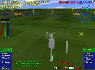
automatically. Figure 6‑13 shows a sample VR view of the Tinmith-Metro
application, with the world as well as an avatar to represent the user standing
on the landscape. The parts of the user’s body are defined as a collection of
cylinders, but each is in coordinates relative to their adjoining parts. For
example, the torso is the main cylinder, and the upper arms, upper legs, and
neck are attached to this. The lower arms are attached to the upper arm, the
hands are attached to the lower arms, and similarly for the legs and feet. The
view frustum representing the user’s field of view is attached to the head,
which is relative to the torso. To make the avatar model mimic the human in the
physical world, scene graph nodes are configured to listen to updates from
tracking devices. For example, a GPS position tracker is attached to the torso
and an IS-300 orientation tracker is attached to the head. As the GPS tracker
is moved about the physical world, the entire body of the avatar will move
about the virtual world. When the IS-300 is rotated, the head as well as the
view frustum of the user is rotated to match. Performing this direct linkage
between tracker and scene graph objects is very easy and intuitive since there
is no need to deal with complex angle or matrix operations. Any transformations
that need to be applied (such as a 90 degree offset or inversion) can be
described in the scene graph itself, avoiding the need to implement extra
external objects to process the tracker data directly.
|
|
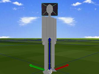
The thumb tracker described previously in Chapter 5 is also implemented using the scene graph. The coordinates returned by the ARToolKit libraries (described further in Chapter 7) are relative to the camera and require further processing to calculate world coordinates. By attaching the thumb tracker to a node relative to the avatar’s view frustum, the scene graph can render 3D cursors at the appropriate location in world coordinates. As the user rotates their head around, these cursors will always be shown at the correct position relative to the avatar’s body. An interesting feature of the scene graph is that any of the nodes may also be used as a source of information for other objects to listen to using data flow. The 2D cursors on the display in Chapter 5 are implemented by listening to the final 3D transformation of the cursors relative to the head and then projecting these to draw a 2D cursor, independent of the scene graph. In this example the scene graph is being used as a kind of calculation engine to perform most of the difficult calculations with the final value being extracted out and used separately. The scene graph allows the graphical specification and preview of transformations, and the rendering can be disabled once debugged and if the results are only exported to other objects.
1.8.3 Indoor ceiling tracking
The
concept of a scene graph calculation engine is used extensively in an indoor
position tracking system being developed [PIEK03e] [PIEK04b]. This tracker is
designed to be cheap and simple to deploy, using cameras mounted on the
backpack to track fiducial markers placed on the ceiling using ARToolKit, as shown
in Figure 6‑14. Although most of the research performed for this
dissertation is outdoor-based, being able to walk indoors and perform similar
modelling operations is also desirable.
|
|
|
Figure 2‑14 Indoor tracking system with backpack, head and shoulder mounted video cameras, GPS antenna, and fiducial markers on the hands, walls and ceiling |
This prototype tracking system incorporates two shoulder mounted cameras (facing forwards and backwards at 45 degree elevations) as well as the existing video overlay head camera. The video cameras capture images of the fiducial markers mounted to the ceiling. Each marker is stored as a translation from an origin point in the room, as well as an orientation from the ceiling and the various walls. With the ARToolKit returning 4x4 transformations of the markers in camera coordinates, these can be transformed into world coordinates by using the existing information known about the markers. Each room and the markers contained within are modelled in the scene graph, and by attaching the 4x4 transformation to the marker the world coordinates for the camera can be calculated. The results measured by the three cameras will each be different due to their different locations on the body, and so they must first be transformed into the same coordinates. Using a simple average without transformations is not feasible since the cameras are separated and not all tracking at the same time. Another problem is that while the shoulder cameras are rigidly mounted, the head camera is articulated on the user’s neck. Since the orientation of each camera is computed using ARToolKit, a fixed transformation can be applied to the shoulder cameras to find a point on the torso of the user. For the articulated head, a transformation is applied along the direction of viewing to the centre of the head, and then a further transform is applied from the joint in the neck to reach a similar torso point as before.
Using the scene graph with graphical visualisation makes the understanding and specification of the transformations relatively simple compared to modelling it with matrices. The scene graph takes inputs from the cameras, transforms them into similar positions, and returns these back as data objects. These data objects are then input to an averaging filter object that produces a final tracker value in world coordinates. This tracker produces output using the same coordinate system as the standard GPS tracker, and so can be easily integrated with the existing tracking system. An object monitors the indoor roof tracker and GPS receiver, passing on a final computed position to the scene graph based on these two inputs.
1.8.4 DIS protocol support
The original DIS protocol based collaboration work performed previously [PIEK99c] has been rewritten for this new software architecture. Entity state updates arriving from the network contain a unique set of identifier values (such as site, host, and entity id) to separate it from other entities. Instead of having a separate internal list of objects, the scene graph is used to represent each entity at a path location such as /models/world/dis/S#/H#/E#, where S# is the site id, H# is the host id, and E# is the entity id. As the position and orientation values are extracted from the DIS entity state PDU packet [IEEE93], they are converted into a 6DOF matrix and then pushed directly into the scene graph. This method treats the DIS update the same as a tracking device, with the numeric id values used to directly identify the correct node in the scene graph. Each entity can be represented using a 3D model for realistic rendering and updated in real-time as packets arrive. Examples of the DIS protocol support are described further in the appendix of this dissertation.
1.8.5 User interface
The
command entry system described in Chapter 5 is implemented as a nested series
of menu objects contained within the object store. The hierarchical nature of
the object store is also used to represent the arrangement of the menu nodes,
and any node in the menu can be referenced using a file system path. These
menus are defined separately from the implementation and are interpreted
dynamically so they can be rearranged without modifying the source code. Menu
nodes are defined to be either of an action or selection type and are connected
together using the storage hierarchy. Action menu nodes contain a command that
is executed internally in the system followed by a relative or absolute path
name of the menu node to visit next. Selection nodes contain a list of child
nodes to include in a menu display, and define a human readable label for
presentation to the user.
|
|
Figure 6‑15 depicts a more detailed definition of a section of the menu previously presented in Figure 5‑14, containing the commands assigned to some menu nodes and the node that will be visited next. Other nodes not showing commands are selection nodes that present the child nodes as choices to the user. Since command nodes cannot contain both a command and a list of children to select from, examples such as nudge execute the start command and then move to a child node called active which is a selection menu containing other children. When a selection menu node is chosen by the user, the menu processor moves its current traversal pointer to the node and refreshes the menu with the list of the new children available for selection. When a command menu node is selected, the command execution engine takes the text-based command string and maps it to an internal method call on the matching Tinmith object. After the execution of the action the traversal pointer is set to point to the next path specified by the menu node. The MIKE system by Olsen [OLSE86] implements a similar idea of decoupling the definition and implementation of menus.
1.8.6 Miniaturised hardware
One of the goals of the software architecture was to be able to develop applications for a wide range of computers. Currently the main demonstration applications operate on a Pentium-III 1.2 GHz laptop with an NVidia GeForce2 OpenGL video accelerator. In the future, I would like to use Tinmith-evo5 applications on smaller laptops and hand-held computers that have less processing power than I am currently using. To verify performance on slower and less capable hardware, the testing platform used is based on a Pentium-I 133 MHz embedded computer with 64 mb of memory and a Chips and Technologies 65555 2D video chipset. This older platform serves as a guide on whether these goals are achievable without requiring a major investment in porting the software to a new platform. With current hand-held computers approaching the capabilities of older processors, this is a very suitable test case that is easy to implement. As proof that this is possible, Wagner and Schmalstieg have demonstrated ARToolKit and OpenGL running on a small hand-held system [WAGN03].
Since the slower testing platform has the same processor architecture as the main platform, the software requires no changes to be compiled. Initially tested were applications that do not perform any rendering, such as the tracker driver for the ARQuake system described in the appendix. For these applications, there is no noticeable performance difference compared to a faster machine since the task of processing tracker inputs and generating packets is relatively simple. This demonstrates that the software architecture can operate within the limited processing and memory resources available for the implementation of simple tasks.
The full Tinmith-Metro application was also tested on the slower testing platform, but some changes were required in order to make the software run. The C&T 65555 chipset does not support any 3D acceleration and so the OpenGL libraries fall back to a software emulation mode that is very slow and inefficient. Generating a single frame takes many seconds and so this is not useful as a real-time AR system. Bellard has developed a small open source emulation library named TinyGL [BELL02], which provides much of the functionality of OpenGL but leaves out many of the more complex operations such as transparency, complex texture mapping, and strict adherence to the specifications. This library is capable of providing 3D rendering with textures on very old computers, although the objects in the environment cannot be as complex as is possible with hardware acceleration. TinyGL was integrated into the system and modifications were made to support the rendering of transparent textures for drawing fonts and to add some OpenGL function calls that were not implemented. The optical overlay mode of the software was also required to be used because the system is not powerful enough to handle the capture and display of video frames from the camera in real-time. With these modifications, the Tinmith-Metro software was able to run at a relatively slow rate of 2-4 frames per second at 640x480 resolution. When the application is profiled, the majority of the CPU time is spent inside the TinyGL code performing rendering. Based on these tests, OpenGL rendering is the main bottleneck affecting the performance of applications, and the software architecture itself has negligible overhead. Given the increasing number of miniaturised computers that include some 3D hardware acceleration, these performance problems will become negligible in the near future.
1.9 Summary
This chapter has described the Tinmith-evo5 software architecture, explaining the advantages of my integrated and uniform approach to building applications for virtual environments, especially mobile AR. The architecture uses a data flow methodology with an object-oriented design to allow applications to be implemented by connecting processing objects together. An object store is developed that is based on Unix file system semantics to provide a simple model for the storage and retrieval of objects in large and complex applications. Using this software architecture, a number of powerful features such as distributed programming, persistent storage, and run time configuration are possible. Components such as a scene graph, a constructive solid geometry engine, and a sensor processing interface are fully integrated to support the requirements of 3D virtual environments. The design is based on the C++ language and although the language has a number of limitations, these are overcome using a variety of techniques. The use of C++ allows the development of efficient applications that operate on a wide range of mobile computers. The applications described in this chapter and in this dissertation are implemented using this software architecture and demonstrate its usefulness for real world applications.