interactive 3d modelling in outdoor augmented reality
worlds


Research Thesis for the Degree of Doctor of Philosophy
By Wayne Piekarski
Bachelor of Engineering in Computer Systems
Engineering (Hons), University of South Australia
wayne@cs.unisa.edu.au
Supervisor
Dr. Bruce Thomas
Adelaide, South Australia
February 2004
|
Wearable Computer
Lab
School of Computer and Information Science
Division of
Information Technology, Engineering, and the Environment
The University of South Australia
|

|
Table of Contents
Chapter 1 - Introduction............................................................................................................ 1
1.1 Problem statement............................................................................................................ 4
1.2 Thesis statement............................................................................................................... 6
1.3 Contributions................................................................................................................... 7
1.4 Dissertation structure....................................................................................................... 8
Chapter 2 - Background........................................................................................................... 10
2.1 Definition of augmented reality..................................................................................... 10
2.2 Applications................................................................................................................... 12
2.3 See through display technology..................................................................................... 20
2.4 3D tracking technology.................................................................................................. 25
2.5 Desktop direct manipulation techniques........................................................................ 38
2.6 Virtual reality interaction techniques............................................................................. 39
2.7 Physical world capture techniques................................................................................. 51
2.8 CAD modelling.............................................................................................................. 55
2.9 Outdoor augmented reality wearable
computers........................................................... 60
2.10 Summary...................................................................................................................... 64
Chapter 3 - Augmented reality working planes....................................................................... 65
3.1 Distance estimation cues................................................................................................ 66
3.2 AR working planes definition........................................................................................ 70
3.3 Coordinate systems........................................................................................................ 72
3.4 Plane creation................................................................................................................. 76
3.5 Object manipulation....................................................................................................... 80
3.6 Vertex placement........................................................................................................... 82
3.7 Accurate alignment with objects.................................................................................... 82
3.8 Alignment accuracy using HMDs.................................................................................. 83
3.9 Summary........................................................................................................................ 89
Chapter 4 - Construction at a distance..................................................................................... 90
4.1 Technique features......................................................................................................... 90
4.2 Direct object placement techniques............................................................................... 95
4.3 Body-relative plane techniques...................................................................................... 97
4.4 AR working planes techniques.................................................................................... 103
4.5 Integrated example...................................................................................................... 110
4.6 Operational performance.............................................................................................. 111
4.7 Summary...................................................................................................................... 112
Chapter 5 - User interface...................................................................................................... 114
5.1 Design rationale........................................................................................................... 114
5.2 Cursor operations......................................................................................................... 117
5.3 Command entry........................................................................................................... 123
5.4 Display interface.......................................................................................................... 127
5.5 Tinmith-Metro modelling application.......................................................................... 132
5.6 Informal user evaluations............................................................................................. 138
5.7 Future work.................................................................................................................. 142
5.8 Summary...................................................................................................................... 143
Chapter 6 - Software architecture.......................................................................................... 144
6.1 Design overview.......................................................................................................... 145
6.2 Previous work.............................................................................................................. 147
6.3 Object design............................................................................................................... 152
6.4 Object storage.............................................................................................................. 156
6.5 Implementation internals.............................................................................................. 161
6.6 Sensors and events....................................................................................................... 168
6.7 Rendering..................................................................................................................... 172
6.8 Demonstrations............................................................................................................ 174
6.9 Summary...................................................................................................................... 181
Chapter 7 - Hardware............................................................................................................ 182
7.1 Hardware inventory..................................................................................................... 182
7.2 Tinmith-Endeavour backpack...................................................................................... 184
7.3 Glove input device....................................................................................................... 193
7.4 Summary...................................................................................................................... 200
Chapter 8 - Conclusion.......................................................................................................... 201
8.1 Augmented reality working planes.............................................................................. 201
8.2 Construction at a distance............................................................................................ 202
8.3 User interfaces............................................................................................................. 203
8.4 Vision-based hand tracking......................................................................................... 203
8.5 Modelling applications................................................................................................. 204
8.6 Software architecture................................................................................................... 204
8.7 Mobile hardware.......................................................................................................... 204
8.8 Future work.................................................................................................................. 205
8.9 Final remarks................................................................................................................ 207
Appendix A - Evolutions....................................................................................................... 208
A.1 Map-in-the-Hat (1998)................................................................................................ 208
A.2 Tinmith-2 prototype (1998)......................................................................................... 210
A.3 Tinmith-3 prototype (1999)......................................................................................... 213
A.4 Tinmith-4 and ARQuake prototype (1999)................................................................ 217
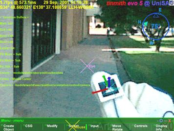
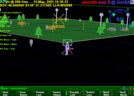
A.5 Tinmith-evo5 prototype one (2001)............................................................................ 218
A.6 Tinmith-VR prototype (2001)..................................................................................... 221
A.7 Tinmith-evo5 prototype two with
Tinmith-Endeavour (2002)................................... 222
A.8 ARQuake prototype two with
Tinmith-Endeavour (2002)........................................ 224
A.9 Summary..................................................................................................................... 226
Appendix B - Attachments.................................................................................................... 227
B.1 CD-ROM.................................................................................................................... 227
B.2 Internet........................................................................................................................ 228
References.............................................................................................................................. 229
List of Figures
Figure 1‑1.... Example
Sony Glasstron HMD with video camera and head tracker.................. 2
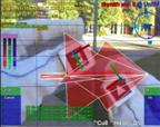
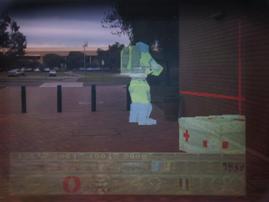
Figure 1‑2.... Example
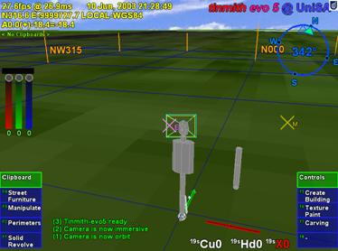
of outdoor augmented reality with computer-generated furniture........ 3
Figure 1‑3.... Schematic
of augmented reality implementation using a HMD........................... 3
Figure 2‑1.... Example
of Milgram and Kishino’s reality-virtuality continuum....................... 11
Figure 2‑2.... The
first head mounted display, developed by Ivan Sutherland in 1968........... 13
Figure 2‑3.... External
and AR immersive views of a laser printer maintenance application... 13
Figure 2‑4.... Virtual
information windows overlaid onto the physical world......................... 14
Figure 2‑5.... Worker
using an AR system to assist with wire looming in aircraft assembly... 15
Figure 2‑6.... AR
with overlaid ultrasound data guiding doctors during needle biopsies....... 15
Figure 2‑7.... Studierstube
AR environment, with hand-held tablets and widgets................. 16
Figure 2‑8.... Marker
held in the hand provides a tangible interface for viewing 3D objects.. 16
Figure 2‑9.... Actors
captured as 3D models from multiple cameras overlaid onto a marker.. 17
Figure 2‑10.. Touring
Machine system overlays AR information in outdoor environments.... 18
Figure 2‑11.. BARS
system used to reduce the detail of AR overlays presented to the user. 18
Figure 2‑12.. Context
Compass provides navigational instructions via AR overlays.............. 19
Figure 2‑13.. Schematic
of optical overlay-based augmented reality...................................... 22
Figure 2‑14.. Optically
combined AR captured with a camera from inside the HMD............ 23
Figure 2‑15.. Schematic
of video overlay-based augmented reality........................................ 23
Figure 2‑16.. Example
video overlay AR image, captured directly from software................. 25
Figure 2‑17.. Precision
Navigation TCM2 and InterSense InertiaCube2 tracking devices..... 37
Figure 2‑18.. CDS
system with pull down menus and creation of vertices to extrude solids. 43
Figure 2‑19.. CHIMP
system with hand-held widgets, object selection, and manipulation... 43
Figure 2‑20.. Immersive
and external views of the SmartScene 3D modelling environment.. 44
Figure 2‑21.. Partial
UniSA campus model captured using manual measuring techniques..... 53
Figure 2‑22.. Screen
capture of Autodesk’s AutoCAD editing a sample 3D model............... 56
Figure 2‑23.. Venn
diagrams demonstrating Boolean set operations on 2D areas A and B.... 58
Figure 2‑24.. CSG
operations expressed as Boolean sets of 3D objects.................................. 58
Figure 2‑25.. Plane
equation divides the universe into two half spaces, inside and outside... 59
Figure 2‑26.. Finite
cylinder defined by intersecting an infinite cylinder with two planes..... 59
Figure 2‑27.. Box
defined using six plane equations and CSG intersection operator............. 60
Figure 2‑28.. Wearable
input devices suitable for use in outdoor environments..................... 62
Figure 3‑1.... 3D
objects are projected onto a plane near the eye to form a 2D image............ 66
Figure 3‑2.... Normalised
effectiveness of various depth perception cues over distance........ 69
Figure 3‑3.... Graph
of the size in pixels of a 1m object on a HMD plane 1m from the eye... 70
Figure 3‑4.... Coordinate
systems used for the placement of objects at or near a human........ 72
Figure 3‑5.... World-relative
AR working planes remain fixed during user movement........... 73
Figure 3‑6.... Location-relative
AR working planes remain at the same bearing from the user and maintain a
constant distance from the user......................................................................................... 74
Figure 3‑7.... Body-relative
AR working planes remain at a fixed orientation and distance to the hips and
are not modified by motion of the head......................................................................... 75
Figure 3‑8.... Head-relative
AR working planes remain attached to the head during all movement, maintaining
the same orientation and distance to the head.......................................................... 76
Figure 3‑9.... AR
working plane created along the head viewing direction of the user.......... 77
Figure 3‑10.. AR
working plane created at a fixed offset and with surface normal matching the
view direction of the user...................................................................................................................... 77
Figure 3‑11.. AR
working plane created at intersection of cursor with object, and normal
matching the user’s view direction.............................................................................................................. 78
Figure 3‑12.. AR
working plane created relative to an object’s surface.................................. 78
Figure 3‑13.. AR
working plane created at a nominated object based on the surface normal of
another reference object.................................................................................................................. 79
Figure 3‑14.. Manipulation
of an object along an AR working plane surface......................... 79
Figure 3‑15.. Depth
translation from the user moving a head-relative AR working plane...... 79
Figure 3‑16.. AR
working plane attached to the head can move objects with user motion.... 79
Figure 3‑17.. Scaling
of an object along an AR working plane with origin and two points.... 80
Figure 3‑18.. Rotation
of an object along AR working plane with origin and two points...... 80
Figure 3‑19.. Vertices
are created by projecting the 2D cursor against an AR working plane 81
Figure 3‑20.. AR
working plane attached to the head can create vertices near the user......... 81
Figure 3‑21.. Example
fishing spot marked using various shore-based landmarks.................. 83
Figure 3‑22.. Example
of range lights in use to indicate location-relative to a transit bearing 83
Figure 3‑23.. Sony
Glasstron HMD measured parameters and size of individual pixels......... 84
Figure 3‑24.. Distant
landmarks must be a minimum size to be visible on a HMD................. 85
Figure 3‑25.. Dotted
lines indicate the angle required to separate the two marker’s outlines. 85
Figure 3‑26.. Similar
triangles used to calculate final positioning error function..................... 86
Figure 3‑27.. Rearrangement
and simplification of final positioning error equation............... 87
Figure 3‑28.. Derivation
of alignment equation when marker B is at an infinite distance....... 87
Figure 3‑29.. 3D
surface plot with marker distances achieving alignment accuracy of 2 cm.. 88
Figure 3‑30.. 3D
surface plot with marker distances achieving alignment accuracy of 50 cm 89
Figure 4‑1.... AR
view of virtual table placed in alignment with physical world table........... 95
Figure 4‑2.... VR
view of bread crumbs markers defining a flat concave perimeter............... 96
Figure 4‑3.... AR
view showing registration of perimeter to a physical world grassy patch... 96
Figure 4‑4.... Example
bread crumbs model extruded to form an unbounded solid shape..... 97
Figure 4‑5.... Infinite
carving planes used to create a convex shape from an infinite solid..... 98
Figure 4‑6.... Orientation
invariant planes generated using multiple marker positions.......... 100
Figure 4‑7.... Relationship
between GPS accuracy and required distance to achieve better than 1 degree of
orientation error for two different GPS types.................................................. 100
Figure 4‑8.... Orientation
invariant planes formed using first specified angle and markers... 101
Figure 4‑9.... Box
objects can be moved into a building surface to carve out windows....... 102
Figure 4‑10.. Convex
trapezoid and concave T, L, and O-shaped objects............................ 103
Figure 4‑11.. Concave
object created using CSG difference of two convex boxes.............. 103
Figure 4‑12.. AR
working planes are used to specify vertices and are projected along the surface
normal for carving the object’s roof................................................................................................ 104
Figure 4‑13.. AR
view of infinite planes building created with sloped roof......................... 105
Figure 4‑14.. AR
view of infinite planes building being interactively carved with a roof.... 105
Figure 4‑15.. VR
view of building with sloped roof, showing overall geometry.................. 105
Figure 4‑16.. Frames
of automobile carving, with markers placed at each corner................. 106
Figure 4‑17.. Final
resulting automobile shown overlaid in AR view, and in a VR view..... 106
Figure 4‑18.. Schematic
illustrating the painting of a window onto a wall surface............... 107
Figure 4‑19.. Examples
showing surface of revolution points for tree and cylinder objects. 107
Figure 4‑20.. AR
view of surface of revolution tree with markers on AR working plane..... 108
Figure 4‑21.. VR
view of final surface of revolution tree as a solid shape............................ 108
Figure 4‑22.. Outdoor
stack of pallets approximating a box, before modelling.................... 109
Figure 4‑23.. VR
view of final model with captured geometry and mapped textures.......... 109
Figure 4‑24.. AR
view of final abstract model, including street furniture items................... 111
Figure 4‑25.. VR
view of final abstract model, including street furniture items................... 111
Figure 5‑1.... Each
finger maps to a displayed menu option, the user selects one by pressing the
appropriate finger against the thumb.............................................................................................. 117
Figure 5‑2.... Immersive
AR view, showing gloves and fiducial markers, with overlaid modelling cursor
for selection, manipulation, and creation................................................................................ 118
Figure 5‑3.... Translation
operation applied to a virtual tree with the user’s hands............... 120
Figure 5‑4.... Scale
operation applied to a virtual tree with the user’s hands......................... 121
Figure 5‑5.... Rotate
operation applied to a virtual tree with the user’s hands...................... 122
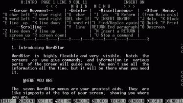
Figure 5‑6.... Original
WordStar application, showing menu toolbar at bottom of screen.... 124
Figure 5‑7.... Immersive
AR overlay display components explained..................................... 128
Figure 5‑8.... Top
down aerial view of VR environment in heading up and north up mode. 129
Figure 5‑9.... Orbital
view centred on the user with a VR style display................................ 129
Figure 5‑10.. User,
view plane, 3D world objects, and distant projection texture map......... 131
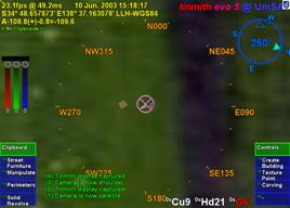
Figure 5‑11.. Immersive
view of Tinmith-Metro with 3D cursor objects appearing to be floating over the
incoming video image....................................................................................................... 132
Figure 5‑12.. External
view of Tinmith-Metro with user’s body and 3D environment......... 132
Figure 5‑13.. Options
available from the top-level of Tinmith-Metro’s command menu...... 133
Figure 5‑14.. Menu
hierarchy of available options for the Tinmith-Metro application.......... 134
Figure 5‑15.. Original
horizontal menu design in immersive AR view.................................. 139
Figure 5‑16.. View
of the user interface being tested in a VR immersive environment........ 140
Figure 6‑1.... Overall
architecture showing sensors being processed using libraries and application
components, and then rendered to the user’s HMD..................................................................... 146
Figure 6‑2.... Layers
of libraries forming categories of objects available to process data...... 153
Figure 6‑3.... Data
values flow into a node for processing, producing output values............ 153
Figure 6‑4.... Expanded
view of data flow model showing stages of processing................. 154
Figure 6‑5.... Network
distribution is implemented transparently using automatically generated
serialisation callbacks and a network transmission interface............................................................... 156
Figure 6‑6.... Examples
demonstrating usage of the hierarchical object store....................... 158
Figure 6‑7.... Simplified
layout of composite Position class, showing nested objects........... 160
Figure 6‑8.... Edited
extract from the is-300.h orientation tracker C++ definition file......... 162
Figure 6‑9.... Complete
XML serialisation of the IS-300 orientation tracker object............. 163
Figure 6‑10.. C++
code demonstrating setup and execution of callbacks............................. 164
Figure 6‑11.. Mathematical
operations possible between absolute and relative objects........ 169
Figure 6‑12.. Distorted
view of Tinmith-Metro showing improperly placed avatar objects when the
resolution of OpenGL’s internal values is exceeded............................................................. 170
Figure 6‑13.. User
is represented in the 3D world with a hierarchical avatar model............. 176
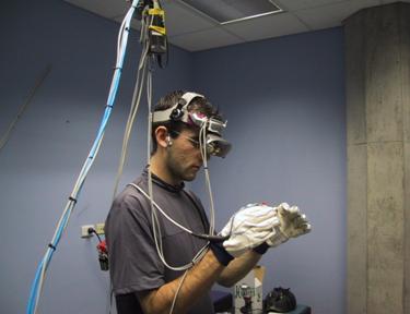
Figure 6‑14.. Indoor
tracking system with backpack, head and shoulder mounted video cameras, GPS
antenna, and fiducial markers on the hands, walls and ceiling.............................................. 177
Figure 6‑15.. Partial
layout of manipulation menu, with internal commands and next path. 179
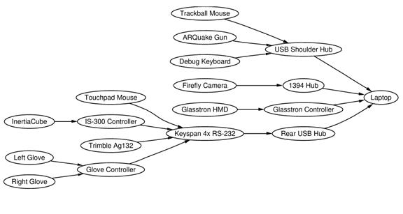
Figure 7‑1.... Data
bus interconnect diagram of components used for mobile outdoor AR.. 184
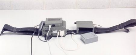
Figure 7‑2.... Rear
view of previous backpack design, showing tangled mess of cabling..... 185
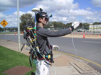
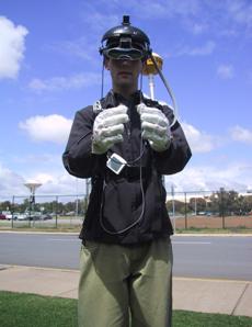
Figure 7‑3.... Front
and rear views of the Tinmith-Endeavour backpack in use outdoors..... 185
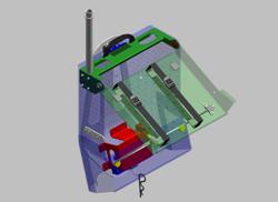
Figure 7‑4.... Design
of polycarbonate housing with hinged laptop holder and internals..... 187
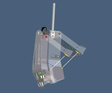
Figure 7‑5.... Backpack
shown in desktop configuration, permitting normal use outside..... 187
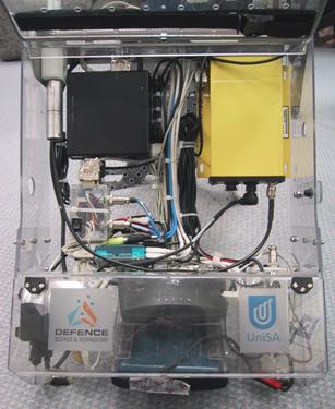
Figure 7‑6.... Interior
of backpack housing, showing internal components and cabling........ 188
Figure 7‑7.... Power
supply breakout box, with +5V, +9V, and +12V at each connector.... 189
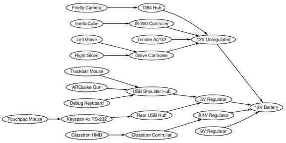
Figure 7‑8.... Power
bus interconnect diagram of components used for mobile outdoor AR 190
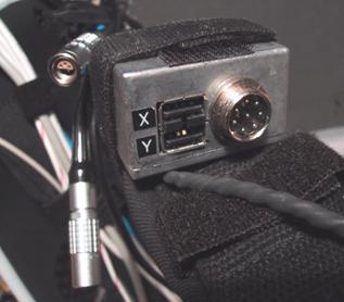
Figure 7‑9.... Two
USB ports, glove connector, and cables mounted onto shoulder straps.. 190
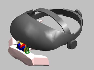
Figure 7‑10.. Design
of brackets to attach Sony Glasstron and Firefly camera to a helmet.. 191
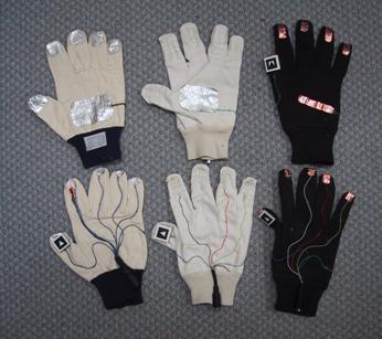
Figure 7‑11.. Designs
of various versions of the glove and attached fiducial markers.......... 194
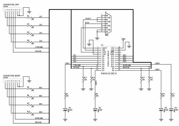
Figure 7‑12.. Circuit
schematic for the low power glove controller....................................... 195
Figure 7‑13.. Example
use of the fiducial marker tracking used for a 3D cursor.................. 196
Figure 7‑14.. ARToolKit
default camera_para.dat file, with error x=2.5, y=48.0................. 198
Figure 7‑15.. Graphical
depictions showing original and new orthogonal camera model..... 199
Figure A‑1... Phoenix-II
wearable computer with batteries, cables, and belt mounting........ 209
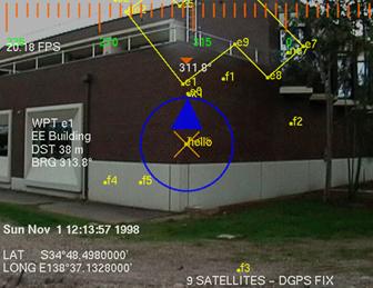
Figure A‑2... Map-in-the-Hat
prototype inside ruck sack, with antenna, cables, and HMD. 209
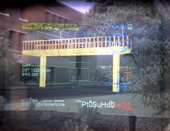
Figure A‑3... Screen
shots of Map-in-the-Hat indicating a waypoint on the display............ 209
Figure A‑4... Tinmith-2
hiking frame with some equipment attached................................... 211
Figure A‑5... 2D
top down map overlaid on physical world (using offline AR overlay)...... 212
Figure A‑6... 2D
top down map overlay with current location relative to nearby buildings. 212
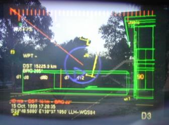
Figure A‑7... 3D
wireframe overlay of building, with small extension made to the left....... 213
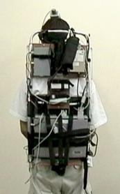
Figure A‑8... Tinmith-3
backpack with HMD, head tracker, and forearm keyboard............ 214
Figure A‑9... Software
interconnect diagram for Tinmith-2 to Tinmith-4 prototypes........... 215
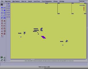
Figure A‑10. View
of ModSAF tool with simulated entities and a wearable user................ 215
Figure A‑11. Wearable
user in outdoor environment generates DIS packets........................ 216
Figure A‑12. MetaVR
view of avatar for wearable user and helicopter for ModSAF entity 216
Figure A‑13. DIS
entities overlaid in yellow on HMD with a top down view..................... 216
Figure A‑14. Visualising
artificial CAD building extensions overlaid on physical world..... 217
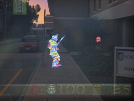
Figure A‑15. ARQuake
implemented using optical AR with virtual monsters shown.......... 218
Figure A‑16. Mock
up demonstrating how a modelling system could be used outdoors...... 219
Figure A‑17. Side
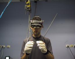
view of original Tinmith-evo5 backpack, with cabling problems............. 220
Figure A‑18. Close
up view of messy cable bundles and miscellaneous input devices......... 220
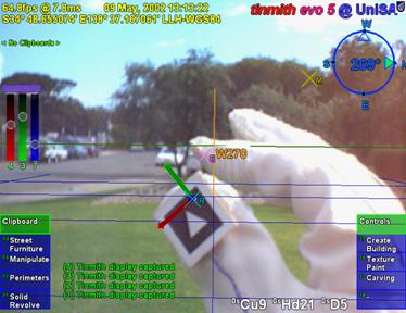
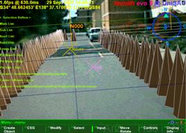
Figure A‑19. Screen
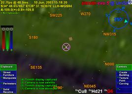
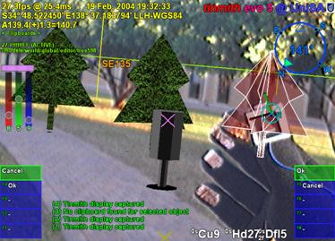
shots of the first Tinmith-Metro release in use outdoors...................... 221
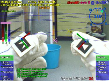
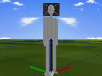
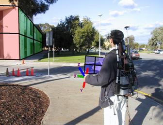
Figure A‑20 VR immersive system used to
control the Tinmith-Metro user interface.......... 222
Figure A‑21. Side
and front views of the Tinmith-Endeavour backpack in use outdoors.... 223
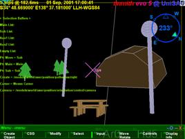
Figure A‑22. Screen
capture of the latest Tinmith-Metro release in use outdoors................. 224
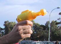
Figure A‑23. USB
mouse embedded into a children’s bubble blowing toy.......................... 225
Figure A‑24. Monsters
overlaid on the physical world with video overlay ARQuake.......... 225
List of Tables
Table 2‑1..... Comparison
between optical and video combined AR systems. 25
Table 2‑2..... Comparison
between various types of 3D tracking technology. 38
Table 2‑3..... Comparison
between forms of VR interaction techniques. 51
Table 3‑1..... Alignment
accuracies for markers at various distances from the user 86
Table 4‑1..... Top down view
of building shapes with vertices (v), edges (e), and facets (f) 94
Table 6‑1..... Approximate
round trip delays experienced for network serialisation. 166
Table 7‑1..... Current
backpack components with cost, location, and power consumption. 183
Abbreviations and Definitions
1394 IEEE Standard 1394,
also referred to as Firewire or i.Link [IEEE95]
2D Two Dimensional in XY
3D Three Dimensional in
XYZ
AAAD Action at a distance,
first defined by Mine [MINE95a]
ACRC Advanced Computing
Research Centre at UniSA
AGD66 Australian Geodetic Datum
1966 [ICSM00]
AGD84 Australian Geodetic Datum
1984 [ICSM00]
AR Augmented Reality
CIS School of Computer and Information Science at UniSA
COTS Commercial Off The Shelf
CRT Cathode Ray Tube
(technology used in television and monitor displays)
CSG Constructive Solid
Geometry
DGPS Differential GPS
DIS IEEE Standard 1278,
the Distributed Interactive Simulation protocol [IEEE93]
DOF Degrees of Freedom ([X,
Y, Z] for position, [q, f, j] for orientation)
3DOF Three degrees of
freedom, only three measurements, such as only orientation or position tracker
information
6DOF Six degrees of freedom,
information about orientation and position, a complete tracking solution
DSTO Defence Science
Technology Organisation, Adelaide, South Australia
ECEF Earth-Centred
Earth-Fixed Cartesian coordinates, in metres [ICSM00]
Evo Evolution or version
number
FOV Field of View, the
angle of the user’s view that a head mounted display or camera can cover
GLONASS Russian Federation, Global
Navigation Satellite System (Global'naya Navigatsionnaya Sputnikovaya Sistema
in Russian)
GPS US Department of Defence, Global Positioning System
HMD Head Mounted Display
HUD Heads Up Display
ITD Information
Technology Division (located at DSTO Salisbury, Adelaide)
IPC Inter-Process
Communication
LCD Liquid Crystal Display
LOD Land Operations
Division (located at DSTO Salisbury, Adelaide)
LLH Latitude Longitude
Height spherical polar coordinates [ICSM00]
LSAP Land Situational
Awareness Picture System
MR Mixed Reality
NFS Sun Microsystems’
Network File System [SAND85]
OEM Original Equipment
Manufacturer
RPC Sun Microsystems’
Remote Procedure Calls
RTK Real-Time Kinematic
(centimetre grade GPS technology)
SERF Synthetic Environment
Research Facility (located at DSTO Salisbury, Adelaide)
SES Scientific and
Engineering Services (located at DSTO Salisbury, Adelaide)
STL Standard Template
Library (for the C++ language)
SQL Server Query Language
Tinmith This Is Not Map In The
Hat (named for historical purposes)
UniSA University of South Australia
USB Universal Serial Bus
UTM Universal Transverse
Mercator grid coordinates, in metres [ICSM00]
VE Virtual Environment
VR Virtual Reality
WCL Wearable Computer Lab at
the University of South Australia
WIM Worlds in Miniature [STOA95]
WIMP Windows, Icons, Menus,
and Pointer
WGS84 World Geodetic System 1984
[ICSM00]
X The X Window System
XML Extensible Mark-up
Language
Summary
This
dissertation presents interaction techniques for 3D modelling of large
structures in outdoor augmented reality environments. Augmented reality is the
process of registering projected computer-generated images over a user’s view
of the physical world. With the use of a mobile computer, augmented reality can
also be experienced in an outdoor environment. Working in a mobile outdoor
environment introduces new challenges not previously encountered indoors,
requiring the development of new user interfaces to interact with the computer.
Current AR systems only support limited interactions and so the complexity of
applications that can be developed is also limited.
This
dissertation describes a number of novel contributions that improve the state
of the art in augmented reality technology. Firstly, the augmented reality
working planes technique gives the user the ability to create and edit objects
at large distances using line of sight and projection techniques. This
technique overcomes limitations in a human’s ability to perceive depth, and
requires simple input devices that are available on mobile computers. A number
of techniques that leverage AR working planes are developed, collectively
termed construction at a distance: street furniture, bread crumbs, infinite
planes, projection carving, projection colouring, surface of revolution, and
texture map capture. These techniques can be used to create and capture the
geometry of outdoor shapes using a mobile AR system with real-time verification
and iterative refinement. To provide an interface for these techniques, a novel
AR user interface with cursors and menus was developed. This user interface is
based around a pair of pinch gloves for command input, and the use of a custom
developed vision tracking system for use in a mobile environment. To develop
applications implementing these contributions, a new software architecture was
designed to provide a suitable abstraction to make development easier. This
architecture is based on an object-oriented data flow approach, uses a special
file system notation object repository, and supports distributed objects. The
software requires a platform to execute on, and so a custom wearable hardware
platform was developed. The hardware is based around a backpack that contains
all the equipment required, and uses a novel flexible design that supports
simple reconfiguration.
Based on these
contributions, a number of modelling applications were developed to demonstrate
the usefulness of these techniques. These modelling applications allow users to
walk around freely outside, and use proprioception and interactions with the hands
to control the task. Construction at a distance allows the user to model
objects such as buildings, trees, automobiles, and ground features with minimal
effort in real-time, and at any scale and distance beyond the user’s reach.
These applications have been demonstrated in the field to verify that the
techniques can perform as claimed in the dissertation.
Declaration
I declare that this thesis does not
incorporate without acknowledgment any material previously submitted for a
degree or diploma in any university and that to the best of knowledge it does
not contain any materials previously published or written by another person
except where due reference is made in the text.
______________________
Wayne Piekarski
Adelaide,
February 2004
______________________
Dr Bruce Thomas – Thesis Supervisor
Adelaide,
February 2004
Acknowledgements
A dissertation does not just appear out
of nowhere, and although it is supposed to be a contribution by one person for
a PhD, there are still a lot of people who have helped me out over the years. I
have been fortunate enough to have had the support of so many people and
without it this would not have been possible. While most people did not help
directly on the project, every one of them contributed in some way towards
helping me to get where I am today, even things like just being a friend and
going out and having fun. Others were responsible for giving me a push in the
right direction in life, and for everyone listed here I am eternally grateful
for their help.
Firstly there is the Wearable Computer
Lab crew. Although I initially started in the lab alone, over the years we have
grown to being a major lab at the university, and I have worked with a number
of people - Ben Close, Hannah Slay, Aaron Toney, Ben Avery, Ross Smith, Peter
Hutterer, Matthias Bauer, Pierre Malbezin, Barrie Mulley, Matthew Schultz,
Scott Sheridan, Leonard Teo, John Squires, John Donoghue, Phil DeBondi, and Dan
Makovec. Many of us have spent many countless late nights working on projects
to meet deadlines and the spirit of our team is truly awesome.
In the CIS department I also have a
number of friends apart from those in the WCL who I go to lunch with almost
every day, and I also enjoy spending time with them outside of work hours -
Grant Wigley, Greg Warner, Malcolm Bowes, Stewart Itzstein, and Toby Richer. I
would especially like to thank Grant for his friendship during the PhD program,
as we both started at the same time and have helped each other out
considerably. On behalf of the lunch crew I would also like to express
gratitude to the Brahma Lodge Hotel, for serving up copious amounts of the
finest cheesy potatoes on the planet to fuel our lunch time cravings.
In the CIS department I have worked with
three heads of school over the years and each have supported me in my
endeavours - Andy Koronios, Brenton Dansie, and David Kearney. With their
financial and leadership contributions I have been given the resources I need
to complete this PhD and also help to develop the WCL into what it is today.
Staff members in the CIS department have
also been extremely helpful. The numerous general staff performed the many
tasks that are required to keep the department running each day, and were
always very happy to help out when required. They helped to organise my
teaching trips, the ordering of equipment, and dealing with finances. Greg
Warner and Malcolm Bowes ran the department servers and allowed us to perform
unorthodox computer networking in the lab. Frank Fursenko and Tony Sobey also
discussed with me C++ and graphics programming on a number of occasions.
Millist Vincent assisted by proofreading parts of the thesis and provided
technical comments.
The DSTO Land Operations Division with
Victor Demczuk and Franco Principe were initially responsible for donating
various wearable computers and resources to the department. This was used to
start the initial projects in the WCL and would not have existed without them.
The Information Technology Division at DSTO has also been instrumental in
further research work we have done, giving us a number of large grants for
equipment as well as the design of our new backpack. I would especially like to
thank Rudi Vernik for his vision in granting this funding to the WCL and it has
helped to make our research first class work. The SES group with John Wilson,
Paul Zalkauskas, Chris Weckert, and Barry Crook, led by Peter Evdokiou, have to
be the finest and most professional group of engineers I have ever met.
Together they manufactured the Tinmith-Endeavour backpack design which dazzles
people at conferences all over the world.
When I was still growing up in 1993, I
had the fortune of using an Internet dial up service run by Mark Newton. He
introduced me to the one true operating system Unix, and all its amazing
features. I used his machine to learn how to use Unix and the fledgling
Internet, and through this I met a number of other people in the area. The late
Chris Wood took the time to teach me how to write Makefiles, use Emacs (the one
true editor), and how to correct bugs in my first X11 application. These
contributions helped to steer my professional development toward Unix
development which would come into much use at university. The Linux community
has also supported me by inviting me to speak at most of their conferences,
allowing me to teach audiences about my research work and to learn from others.
The developers who donated their time to the development of drivers for the
hardware I use have been most helpful, without these this project would not
have been possible.
When I was just starting at university I
was fortunate enough to meet Steve Baxter. He had just started up an Internet
company called SE Net along with his wife Emily Baxter and friend Chris Foote,
and asked me to work as the first employee of the company helping with sales
and support. As the company grew I was given the role of Manager of R&D,
and given the task of developing the systems that controlled the entire
company. Steve trusted in my abilities the future of his entire company. This
enabled me to gain a wealth of experience in leadership and design that would
never be given to most 18 year olds, and for this I am very grateful. Together
we built a company that led the field in a number of areas. As part of the team
at SE Net, I have many friends - Matt Altus, David Kuzmak, Richard and Genni
Kaye, Robert Gulley, Andrew Xenides, Rebecca Razzano, Lindsay Whitbread, Megan
Hehir, Mark Mills, and Scott Smith. Unfortunately SE Net has now been absorbed
by the new owners of the company, and so the fine traditions and spirit from SE
Net are no longer around, but exist in our memories forever.
During my travels overseas I have met a
number of great people who have been friendly and helpful. I would like to
especially thank the Computer Science department at the University of North Carolina at Chapel Hill for allowing me to spend three months performing research there.
Sally Stearns and Ray Thomas were kind enough to let me stay at their house for
the first few days while I found a place to stay. At UNC I made many friends
such as Mark Harris, Scott Cooper, Ken Hoff, Benjamin Lok, Samir Nayak, David
Marshburn, Andrew Nashel, and Stefan Sain, as well as the Pi Lambda Phi
fraternity and Drink Club crew.
There are also a number of other people
who do not work with me but have been friends for many years and I would also
like to thank them for their support - David Pridgeon, Trent Greenland, Ghassan
Abi Mosleh, Rebecca Brereton, Donna Harvey, Krishianthi Karunarathna, Josie
Brenko, Tam Nguyen, Sarah Bolderoff, and Derek Munneke.
The most instrumental person for this
dissertation was my supervisor Dr Bruce Thomas. I have worked with Bruce for
the last five years first as a final year undergraduate project student, and
then as a PhD student. Bruce had the insight to move into wearable computers
and augmented reality in the very early days and formed the Wearable Computer
Lab we have today. Bruce has helped me to gain an international profile in the
AR and wearables community, by generously giving me the funding to travel to
numerous places all over the world and to meet other researchers (and obtain a
frequent flyer gold card). This international development has strengthened my
PhD with experience from a wide range of people and further motivated my
research with fresh ideas. I would also like to thank Bruce for the countless
hours I have spent with him discussing research, proof reading papers and this
dissertation, talking about life in general, and having a beer as friends when
travelling.
To achieve a PhD at the University of South Australia, the dissertation must be reviewed by two external experts in the
area of research. I was fortunate enough to have Professor Steven Feiner from Columbia University and Associate Professor Mark Billinghurst from HIT Lab New Zealand as reviewers, who are both outstanding researchers in the international community.
Each of them carefully read through the hundreds of pages of this dissertation
and gave me excellent feedback which has been integrated into this final
version. I would like to thank both of them for their time and dedication to
reviewing my work and helping to improve it.
Most importantly of all, I would like to
thank my mum Kris, dad Spishek, brother Arron, and my grandparents for
supporting me for the last 25 years. My family also helped me build some of the
early backpack prototypes in the garage, making an important contribution to
the project. It is through their encouragement and care that I have made it
through all the steps to reach this point in life, and I couldn’t have done it
without them. When my dad bought me a Commodore 64 when I was a little boy, who
would have thought I would have ended up here today? My family has always taken
care of me and I love them all very much.
In summary, I would like to thank
everyone for putting up with me for the last couple of years. I believe that
this dissertation has made a real contribution to the field of computer science
and I hope that everyone that reads this dissertation finds it useful in their
work. It has been a fun journey so far, and I look forward to catching up with
everyone and having lots of fun and good times, because that is the most
important thing of all.
Now it is time to catch up on some sleep
and have a holiday! (Well, not really - there is still plenty of other work to
do now)
Regards,
______________________
Wayne Piekarski
Adelaide,
February 2004
Inspiration
“Another noteworthy characteristic of
this manual is that it doesn't always tell the truth ... The author feels that
this technique of deliberate lying will actually make it easier for you to
learn the ideas. Once you understand the simple but false rule, it will not be
hard to supplement that rule with its exceptions.”
Donald Knuth, from the preface to The
TeXbook
“If you do choose to use a computer,
beware the temptation it offers to let manuscript preparation displace
composition. They are two separate activities, best done separately.
Hyphenation and exposition are at war with one another. Pagination vies with
content. The mind busy fretting over point size has no time left over to
consider clarity. If you need a break from the ardors of composition, try the
time-honored ones like poking the fire or baking bread. They smell good, and
they don't give you any illusion that your paper is making progress while you
indulge in them.”
Mary-Claire van Leunen
1
"We all agree that your theory is
crazy, but is it crazy enough?"
Niels Bohr (1885-1962)
Augmented reality (AR) is the
registration of projected computer-generated images over a user’s view of the
physical world. With this extra information presented to the user, the physical
world can be enhanced or augmented beyond the user’s normal experience. The
addition of information that is spatially located relative to the user can help
to improve their understanding of it. In 1965, Sutherland described his vision
for the Ultimate Display [SUTH65], with the goal of developing
systems that can generate artificial stimulus and give a human the impression
that the experience is actually real. Sutherland designed and built the first
optical head mounted display (HMD) that was used to project computer-generated
imagery over the physical world. This was the first example of an augmented
reality display [SUTH68]. Virtual reality (VR) was developed
later using opaque display technology to immerse the user into a fully
synthetic environment. One of the first integrated environments was by Fisher
et al., combining tracking of the head for VR with the use of tracked gloves as
an input device [FISH86].
Augmented reality and virtual reality
share common features in that they present computer-generated images for a user
to experience, with information anchored to 3D locations relative to the user’s
display, their body, or the world [FEIN93b]. The physical world seen when
using AR can be thought of as a fourth kind of information that the user can
experience, similar to world-relative display but not artificially generated. A
typical example of a head mounted display is shown in Figure 1‑1, and an
example AR scene with both physical and virtual worlds is depicted in Figure 1‑2.
The schematic diagram in Figure 1‑3 depicts how a see-through HMD (used
to produce AR images for the user) can be conceptualised, and the next chapter
discusses in depth their implementation. While other forms of sensory
stimulation such as haptics and audio are also available to convey information
to the user, these will not be discussed since the focus of this dissertation
is HMD-based AR.
|
Figure 1‑1 Example Sony Glasstron HMD with video camera and head
tracker
|
Although the first HMD was implemented in
1968 and performed augmented reality, the first main area of research with
these devices was for virtual reality. VR has a number of similar research
problems with AR, but does not rely on the physical world to provide images and
can also be viewed on display monitors or projectors. Since the user is
normally tethered to the VR system, they are not able to walk large distances
and virtual movement techniques such as flying are required to move beyond
these limits. These same problems restricted initial AR research because, by
its very nature, the user would like to walk around and explore the physical
world overlaid with AR information without being tethered to a fixed point.
While there are some important uses for AR in fixed locations, such as assisted
surgery with overlaid medical imagery [STAT96] or assistance with assembly tasks [CURT98], the ability to move around freely
is important. When discussing the challenges of working outdoors Azuma states
that the ultimate goal of AR research is to develop systems that “can operate
anywhere, in any environment” [AZUM97b].
A pioneering piece of work in mobile
augmented reality was the Touring Machine [FEIN97], the first example of a mobile
outdoor AR system. Using technology that was small and light enough to be worn,
a whole new area of mobile AR research (both indoor and outdoor) was created. While
many research problems are similar to indoor VR, there are unsolved domain
specific problems that prevent mainstream AR usage. Older survey papers (such
as by Azuma [AZUM97a]) cover many technological problems
such as tracking and registration. As this technology has improved, newer
research is focusing on higher-level problems such as user interfaces, as
discussed by Azuma et al. [AZUM01].
|
Figure 1‑2 Example of outdoor augmented reality with
computer-generated furniture
Figure 1‑3 Schematic of augmented reality implementation using a HMD
|
Many outdoor AR systems produced to date
rely only on the position and orientation of the user’s head in the (sometimes
limited) physical world as the user interface, with user interfaces that can
indirectly adjust the virtual environment. Without a rich user interface
capable of interacting with the virtual environment directly, AR systems are
limited to changing only simple attributes, and rely on another computer
(usually an indoor desktop machine) to actually create and edit 3D models. To
date, no one has produced an outdoor AR system with an interface that allows
the user to leave behind all their fixed equipment and independently perform 3D
modelling in real-time. This dissertation explores user interface issues for
AR, and makes a number of contributions toward making AR systems able to
operate independently in the future, particularly for use in outdoor
environments.
The development of user interfaces for
mobile outdoor AR systems is currently an area with many unsolved problems. When
technology is available in the future that solves existing registration and
tracking problems, having powerful applications that can take advantage of this
technology will be important. Azuma et al. state that “we need a better
understanding of how to display data to a user and how the user should interact
with the data” [AZUM01]. In his discussions of virtual reality
technology, Brooks stated that input devices and techniques that substitute for
real interactions were still an unsolved problem and important for interfacing
with users [BROO97]. While VR is a different
environment in that the user is fully immersed and usually restricted in
motion, the 3D interaction problems Brooks discusses are similar and still
relevant to the AR domain. Working in an outdoor environment also imposes more
restrictions due to its mobile nature, and increases the number of problems to overcome.
On desktop computers, the ubiquitous WIMP
interface (windows, icons, menus, and pointer - as pioneered by systems such as
the Xerox Star [JOHN89]) is the de-facto standard user
interface that has been refined over many years. Since mobile outdoor AR is a
unique operating environment, many existing input methodologies developed for
AR/VR and desktop user interfaces are unavailable or unsuitable for use. In an
early paper about 3D modelling on a desktop, Liang and Green stated that
mouse-based interactions are bottlenecks to designing in 3D because users are
forced to decompose 3D tasks into separate 1D or 2D components [LIAN93]. Another problem is that most
desktop 2D input devices require surfaces to operate on, and these are
unavailable when walking outdoors. Rather than trying to leverage WIMP-based
user interfaces, new 3D interfaces should be designed that take full advantage
of the environment and devices available to the user. An advantage of AR and VR
is that the user’s body can be used to control the view point very intuitively,
although no de-facto standard has emerged for other controls in these
applications. While research has been performed in the VR area to address this,
many techniques developed are intended for use in immersive environments (which
do not have physical world overlay requirements) and with fixed and limiting
infrastructure (preventing portability).
With AR systems today (and with virtual
environments in general), a current problem is the supply of 3D models for the
computer to render and overlay on the physical world. Brooks mentions that 3D
database construction and modelling is one of four technologies that are
crucial for VR to become mainstream, and is still an unsolved problem [BROO97]. He mentions that there is promising
work in the area of image-based reconstruction, but currently modelling is
performed using CAD by-products or hard work. An interesting problem area to
explore is what types of models can be created or captured directly while
moving around outdoors. By integrating the modelling process and user
interface, the user is able to control the modelling process directly and take
advantage of their extensive knowledge of the environment.
1.1.1 Research questions
For this dissertation I have investigated
a number of different unsolved problems in the field of AR, and then combined
the solutions developed to produce real world applications as demonstrations. I
have formulated these different problems into research questions that will be
addressed in this dissertation:
· How can a user intuitively control and interact with a mobile AR
system outdoors, without hampering their mobility or encumbering their hands?
How can
a user perform manipulation tasks (such as translate, rotate, and scale) with
an outdoor mobile AR system of existing 3D geometry, in many cases out of arm’s
reach and at scales larger than the user’s body?
How can
a user capture 3D geometry representing objects that exist in the physical
world, or create new 3D geometry of objects that the user can preview alongside
physical world objects, out of arm’s reach and at scales larger than the user’s
body?
What is
an appropriate software architecture to develop this system with, to operate
using a wide variety of hardware and software components, and to simplify
application development?
What
hardware must be developed and integrated into a wearable platform so that the
user can perform AR in the physical world outdoors?
What
application domains can take advantage of the novel ideas presented in this
dissertation, and for what real world uses can they be applied to?
1.1.2 Research goals
The main goal of this dissertation is to
answer the questions discussed previously and contribute solutions towards the
problems facing augmented reality today, predominantly in the area of user
interfaces for mobile outdoor systems. The specific research goals of this
dissertation are as follows:
· Mobile user interface - The user
interface should not unnecessarily restrict the user’s mobility, and should use
intuitive and natural controls that are simple to learn and use. Requiring the
user to carry and manipulate physical props as controls may interfere with the
user’s ability to perform a required task, such as holding a tool.
Real-time
modelling enhanced with proprioception - The user
should be able to interactively create and capture the geometry of buildings
using the presence of their body. Using solid modelling operations and the
current position and orientation of the head and hands will make this process
intuitive for the user.
Mobile
augmented reality - Outdoor augmented reality
requires a mobile computer, a head mounted display, and tracking of the body.
These technologies currently suffer from a number of limitations and
applications must be designed with this in mind to be realisable. By using
current technology, new ideas can be tested immediately rather than waiting for
future technology that may not appear in the short term.
Using parts of the body such as the head
and hands to perform gestures is a natural way of interacting with 3D
environments, as humans are used to performing these actions when explaining
operations to others and dealing with the physical world. By using techniques
such as pointing and grabbing with objects in positions relative to the body,
user interfaces can leverage proprioception, the user’s inbuilt knowledge as to
what their body is doing. Mine et al. [MINE97a] demonstrated that designing user
interfaces to take advantage of a human’s proprioceptive capabilities produced
improved results. Using an input device such as a mouse introduces extra levels
of abstraction for the direct manipulation metaphor (as discussed by Johnson et
al. [JOHN89]), and so using the head and hands
allows more intuitive controls for view point specification and object
manipulation.
Trying to leverage existing 2D input
devices for use in a naturally 3D environment is the wrong approach to this
problem, and designing proper 3D user interfaces that directly map the user to
the problem (as well as taking advantage of existing interactive 3D research)
will yield improved results. The use of 3D input devices has been demonstrated
to improve design and modelling performance compared to
2D desktop systems that force the user to break down 3D problems into separate
and unnatural 2D operations [CLAR76] [SACH91] [BUTT92] [LIAN93].
In VR environments the user is able to
use combinations of physical movement and virtual flying operations to move
about. In contrast, in AR environments the user is required to always move with
their physical body otherwise registration between the physical and artificial
worlds will be broken. Using direct manipulation
techniques, interacting with objects that are too large or too far away is not
possible. Desktop-based CAD systems rely on 2D inputs but can perform 3D
operations through the use of a concept named working planes. By projecting a
2D input device cursor onto a working plane the full 3D coordinates of it can be
calculated unambiguously. By extending the concept of working planes to
augmented reality, both the creation of geometry and interaction with objects
at a distance can be achieved. These working planes can be created using the
physical presence of the body or made relative to other objects in the
environment. Accurate estimation of the depth of objects at large distances
away has been shown to be difficult for humans [CUTT95], and AR working planes provides
accurate specification of depth. This functionality is achieved using a
slightly increased number of interaction steps and reduction in available
degrees of freedom.
By combining AR working planes with
various primitive 3D objects (such as planes and cubes) and traditional
constructive solid geometry techniques (such as carving and joining objects),
powerful modelling operations can be realised, which I have termed construction
at a distance. These operations give users the capability to capture 3D models
of existing outdoor structures (supplementing existing surveying techniques),
create new models for preview that do not currently exist, and perform editing
operations to see what effect changes have on the environment. By taking
advantage of a fully tracked AR system outdoors, and leveraging the presence of
the user’s body, interactive modelling can be supported in an intuitive
fashion, streamlining the process for many types of real world applications.
This dissertation makes a number of
research contributions to the current state of the art in augmented reality and
user interfaces. Some of the initial contributions in this dissertation also
require a number of supporting hardware and software artefacts to be designed
and developed, each with their own separate contributions. The full list of
contributions is:
· The analysis of current techniques for distance estimation and
action at a distance, and the formulation of a technique named augmented
reality working planes. This new technique can create objects accurately at
large distances through the use of line of sight techniques and the projection
of 2D cursors against planes. This technique is usable in any kind of virtual
environment and is not limited to augmented reality. [PIEK03c]
The
design and implementation of a series of techniques I term construction at a
distance, which allow users to capture the 3D geometry of existing outdoor
structures, as well as create 3D geometry for non-existent structures. This
technique is based on AR and uses the physical presence of the user to control
the modelling. Objects can be modelled that are at scales much larger than the
user, and out of arm’s reach. [PIEK03c]
The
iterative design and development of an augmented reality user interface for
pointing and command entry, allowing a user wearing gloves to navigate through
and select menu options using finger presses, without requiring high fidelity
tracking that is unavailable outdoors. This user interface can operate without
tracking, but when tracking is available it allows interaction at a distance
with 3D environments. [PIEK03d]
The
development of a vision-based hand tracking system using custom designed pinch
gloves and existing fiducial marker tracking software that can work reliably
under outdoor wearable conditions. [PIEK02f]
The
development of applications that allow users to model buildings with the
techniques described in this dissertation, and in some cases being able to
model objects previously not possible with or faster than existing surveying
techniques. [PIEK01b] [PIEK03c]
The
design and implementation of a software architecture that is capable of
supporting the research for this dissertation, culminating in the latest design
of the Tinmith software. Current software architectures are still immature and
do not support all the requirements for this dissertation, and so this
architecture was designed to support these requirements and implements many
novel solutions to various problems encountered during the design. [PIEK01c] [PIEK02a] [PIEK03f]
The
iterative design and development of hardware required to demonstrate the
applications running outdoors. Wearable computing is currently in its infancy
and so the devices that are required to be used outdoors are not necessarily
designed for this, and numerous problems have been encountered for which novel
solutions to these are implemented. [PIEK02h]
After this introduction chapter, chapter
two contains an overall background discussion introducing the concepts and
technology that form a core of this dissertation. This overview provides a
general discussion of related research, and each chapter then includes other
more specific background information when relevant. Chapter three discusses the
problems associated with a user interacting with objects at large distances –
while most VR systems take advantage of a human’s ability to work well within
arm’s reach, outdoor AR work tends to be performed away from the body where
depth perception attenuates very rapidly. The novel idea of using the concept
of CAD working planes for AR is introduced, along with various techniques that
can be employed to perform interaction at a wide range of scales and distances
beyond the reach of the user. Chapter four takes the concepts previously
developed in the dissertation as well as constructive solid geometry and
develops a new series of techniques named construction at a distance that allow
users to perform modelling of outdoor objects using a mobile AR system. These
techniques are then demonstrated using a series of examples of outdoor objects
to show their usefulness. Chapter five explains how the previously developed
techniques are interfaced to the user through pointing with the hands, command
entry using the fingers, and the display of data to the HMD. The user interface
is required to develop applications that are useable tools - an important part
of this dissertation is the ability to test out the techniques and improve them
iteratively. Chapter six introduces the software architecture used to
facilitate the development of virtual environment applications. The software
architecture contains a number of novel features that simplify the programming
of these applications, unifying all the components with a consistent design
based on object-oriented programming, data flow, and a Unix file system-based object
repository. By tightly integrating components normally implemented separately,
such as the scene graph, user interface, and internal data handling,
capabilities that are normally difficult to program can be handled with
relative ease. To complete the research, chapter seven describes the hardware
components that are an important part of the overall implementation since the
software relies on these to execute. The research and development of the mobile
backpack, user input glove, and vision tracking system are explained to show
some of the important new innovations that have been developed in these areas
for use outdoors. After concluding with a discussion of the numerous
contributions made and future work, this dissertation contains an appendix with
a history of my previous hardware and software implementations, as well as
links to where further information can be found about the project.
2
"If you want to make an apple pie
from scratch, you must first create the universe."
Carl Sagan
This chapter contains a summary of the
state of the art in augmented reality research and related technologies that
are relevant to this dissertation. Some of this information has been developed
during the period of my research and is included so comparisons can be made.
First, an extended (from chapter 1) description and definition of augmented
reality is presented, followed by a discussion of how it fits into the spectrum
of virtual environments. The chapter then goes on to discuss various indoor and
outdoor AR applications that have been developed, demonstrating the current
state of the art. Following this is a discussion of the two techniques for
performing real-time AR overlay, as well as a summary of the numerous types of
tracking technologies employed. After these technologies have been explained, a
history of human computer interaction techniques for desktop and virtual
reality systems is then covered. Current techniques used for the capture of
models in the physical world are then discussed, followed by a section
summarising commercially available CAD software and solid modelling techniques.
Finally, the problems of working outdoors with wearable computers are
described, including how they can be used for mobile augmented reality.
When Sutherland proposed the concept of
the Ultimate Display [SUTH65], his goal was to generate
artificial stimulus that would give the user the impression that the experience
is real. Instead of immersing the user into an artificial reality, a second
approach is to augment the user’s senses with extra information, letting them
experience both artificial and real stimulus simultaneously. In his excellent
survey paper of the field, Azuma defines augmented reality systems as those
that contain the following three characteristics [AZUM97a]:
· Combines real and virtual
Interactive
in real-time
Registered
in 3D
This definition does not limit augmented
reality to the use of head mounted displays (allowing for monitors, projectors,
and shutter glasses), but excludes non-interactive media such as movies and
television shows. This dissertation focuses on mobile outdoor augmented
reality, and therefore this chapter will focus only on research related to head
mounted displays.
|

Figure 2‑1 Example of Milgram and Kishino’s reality-virtuality
continuum
(Adapted
from [MILG94])
|
With the availability of real-time
computer-generated 3D graphics, computers can render synthetic environments on
a display device that can give the user the impression they are immersed within
a virtual world. This technology is referred to as virtual reality (VR) and is
designed to simulate with a computer the physical world humans normally can
see. The opposite of VR is the real physical world typically experienced by a
human, although it may be slightly attenuated because it is being viewed via a
head mounted display or video camera. Augmented reality is therefore made up of
a combination of virtual and real environments, although the exact make up of
this may vary significantly. Milgram and Kishino used these properties to
define a reality-virtuality continuum [MILG94], and this can be used to perform
comparisons between various forms of mixed reality by placement onto a
spectrum. At one end of the continuum is the physical world, the other end is
fully synthetic virtual environments, and AR is located somewhere in between
since it is a combination of the two. Figure 2‑1 is adapted from Milgram
and Kishino’s continuum, with example pictures at different locations on the
reality-virtuality spectrum but showing the view from the same location. The
first image in Figure 2‑1 shows a view of the physical world seen through
a head mounted display, with no virtual information at all. The next image is augmented
reality, where artificial objects (such as the table) are added to the physical
world. The third image is augmented virtuality, where physical world objects
(such as a live display of the user’s view of the world) are added into a fully
immersive virtual environment. The final image depicts a completely synthetic
environment, with no information from the physical world being presented. Every
type of 3D environment can be placed somewhere along this spectrum and can be
used to easily compare and contrast their properties.
To overlay 3D models on to the user’s
view, a mobile AR system requires a HMD to be combined with a device that can
measure the position and orientation of the user’s head. As the user moves
through the physical world the display is updated by the computer in real-time.
The accuracy of the virtual objects registered to the physical world influences
the realism of the fusion that the user experiences. A major focus of current
AR research has been achieving good registration, as discussed extensively in
survey papers by Azuma [AZUM97a] and Azuma et al. [AZUM01]. There are a number of known
problems that cause poor registration, such as tracker inaccuracies, HMD
misalignment, and delays in the various stages of rendering from the trackers
to the display.
While registration is important for
producing AR applications that are realistic (giving the user a sense of
presence and hence being more immersive and easier to use) it is not the only
important issue in AR research. Other questions, such as how do users interface
with these systems, and what kind of tasks can systems perform, are also
important and make the registration research useable for building real world applications.
During the evolution of technologies such
as virtual reality and augmented reality, there have been a number of
applications developed that demonstrate the use of this technology. In the
field of augmented reality, this research work initially began indoors where
hardware is able to be large and consume considerable electrical power without
imposing too many restrictions on its use. As hardware has become smaller in
size and more powerful, researchers are demonstrating more complex systems and
are starting to move outdoors. This section discusses various applications that
have been developed for both indoor and outdoor environments, approximately
arranged in chronological order where possible.
2.1.1 Indoor augmented reality
For indoor augmented reality, there are a
number of applications that have been developed in areas as diverse as
information display, maintenance, construction, and medicine. These
applications are used to provide extra situational awareness information to
users to assist with their tasks. By projecting data onto the vision of a user,
information is shown in situ in the environment and the user can better
understand the relationship the data has with the physical world. The first
working AR demonstration was performed using a HMD designed by Sutherland [SUTH68] and is shown in Figure 2‑2.
This HMD is transparent, in that the user can see the physical world as well as
computer-generated imagery from small CRT displays overlaid using a half
silvered mirror. So while the goal of the Ultimate Display concept was to
completely immerse the user’s senses into a virtual environment, Sutherland
actually invented the addition of information (augmented reality) with the
development of this display. Sutherland’s demonstration projected a simple wire
frame cube with line drawn characters representing compass directions on each
wall. Other see through HMDs were developed for use in military applications,
with examples such as the Super Cockpit project by Furness [FURN86]. The use of HMDs was designed to
improve on existing heads up displays (HUD) in military aircraft, providing
information wherever the user is looking instead of just projected onto the
front of the glass windshield. Similar technology is used to implement displays
for virtual reality, except these are opaque and do not use the physical world
to provide extra detail.
|
Figure 2‑2 The first head mounted display, developed by Ivan
Sutherland in 1968
(Reprinted
and reproduced with permission by Sun Microsystems, Inc)
|
|
Figure 2‑3 External and AR immersive views of a laser printer
maintenance application
(Images
courtesy of Steven Feiner – Columbia University)
|
The KARMA system was developed by Feiner
et al. as a test bed for the development of applications that can assist with
3D maintenance tasks [FEIN93a]. Instead of simply generating
registered 3D graphics from a database to display information, KARMA uses
automatic knowledge-based generation of output depending on a series of rules
and constraints that are defined for the task. Since the output is not
generated in advance, the system can customise the output to the current
conditions and requirements of the user. One example demonstrated by Feiner et
al. was a photocopier repair application (shown in Figure 2‑3) where the
user is presented with detailed 3D instructions showing how to replace toner
and paper cartridges.
|
Figure 2‑4 Virtual information windows overlaid onto the physical
world
(Image
courtesy of Steven Feiner – Columbia University)
|
The Windows on the World work by Feiner
et al. demonstrated the overlay of windows with 2D information onto an AR
display [FEIN93b]. While traditional AR systems
render 3D information, this system is based on 2D information in an X Windows
server. Windows of information can be created in the X server and then attached
to the display, the user’s surround, or the physical world. As the user moves
about the 3D environment, the system recalculates the position of the windows
on the HMD. Since the system is based on X Windows, any standard X application
can be used and information always appears facing the user with no perspective
warping. Figure 2‑4 shows an example of 2D information windows attached
to different parts of the environment.
One of the first commercially tested
applications for augmented reality was developed by the Boeing company to
assist with the construction of aircraft [CURT98]. One task performed by workers is
the layout of wiring bundles on looms for embedding into the aircraft under
construction. These wiring looms are complicated and so workers must constantly
refer to paper diagrams to ensure the wires are placed correctly. Curtis et al.
describe the testing of a prototype AR system that overlays the diagrams over
the wiring board so that workers do not have to take their eyes away from the
task. Although it was never fully deployed in the factory, this research is a
good demonstration of how AR technology can be used to assist workers with
complicated real world tasks.
|
Figure 2‑6 AR with overlaid ultrasound data guiding doctors during
needle biopsies
(Image
courtesy of Andrei State – University of North Carolina, Chapel Hill)
|
Using AR to assist doctors with medical
imaging is an area that shows much promise in the near future. A current
problem with X-ray and ultrasound images is that they are two dimensional and
it is difficult to spatially place this information easily within the physical
world. By overlaying this information onto the patient using AR, the doctor can
immediately see how the imaging data relates to the physical world and use it
more effectively. State et al. have been performing research into the overlay
of ultrasound images onto the body to assist with breast biopsies [STAT96]. During the biopsy, a needle is
injected into areas of the body that the doctor needs to take a sample of and
analyse. Normally, the doctor will take many samples and hope that they manage
to achieve the correct location, but damaging areas of tissue in the process.
Using AR, the ultrasound overlay can be used to see where the biopsy needle is
relative to the area of interest, and accurately guide it to the correct
location. This results in less damage to the surrounding tissue and a greater
chance of sampling the desired area. Figure 2‑6 shows an example of a
needle being inserted into a simulated patient with overlaid ultrasound
imagery.
|
Figure 2‑7 Studierstube AR environment, with hand-held tablets and
widgets
(Images
courtesy of Gerhard Reitmayr – Vienna University of Technology)
|
Schmalstieg et al. [SCHM00] and Reitmayr and Schmalstieg [REIT01a] describe a collaborative augmented
reality system named Studierstube, which can perform shared design tasks. In
this environment, users can work together to perform tasks such as painting
objects and direct manipulation of 3D objects, as shown in Figure 2‑7. To
provide users with a wide range of possible operations, the user carries a
Personal Interaction Panel (PIP) [SZAL97]. The PIP can be constructed using
either a pressure sensitive tablet or a tracked tablet and pen combination, and
the AR system then overlays interactive widgets on top of the tablet. Using the
pen on the tablet, the user can control the widgets that are linked up to
various controls affecting the environment.
|
Figure 2‑8 Marker held in the hand provides a tangible interface for
viewing 3D objects
(Images
courtesy of Mark Billinghurst – University of Washington)
|
The ARToolKit was developed by Kato and
Billinghurst to perform the overlay of 3D objects on top of paper fiducial
markers, using only tracking data derived from captured video images [KATO99]. Using this toolkit, a number of
applications have been developed that use tangible interfaces to directly
interact with 3D objects using the hands. Billinghurst et al. [BILL99] use this toolkit to perform video
conferencing, with the user able to easily adjust the display of the remote
user, as shown in Figure 2‑8. Another application that uses this
technology is Magic Book by Billinghurst et al. [BILL01]. Each page of the magic book
contains markers that are used to overlay 3D objects with AR. By pressing a
switch on the display the user can be teleported into the book and experience
immersive VR. Magic Book integrates an AR interface (for viewing the book from
a top down view with a tangible interface) with a VR interface (for immersively
flying around the book’s 3D world).
|
Figure 2‑9 Actors captured as 3D models from multiple cameras
overlaid onto a marker
(Image
courtesy of Adrian Cheok – National University of Singapore)
|
The 3D Live system by Prince et al. [PRIN02] captures 3D models of actors in
real-time that can then be viewed using augmented reality. By arranging a series
of cameras around the actor, Virtual Viewpoint software from Zaxel [ZAX03] captures the 3D geometry using a
shape from silhouette algorithm, and then is able to render it from any
specified angle. 3D Live renders this output onto ARToolKit markers, and live
models of actors can be held in the hands and viewed using easy to use tangible
interfaces, as shown in Figure 2‑9. Prince et al. explored a number of
displays for the system, such as holding actors in the hands on a card, or
placing down life sized actors on the ground with large markers.
2.1.2 Outdoor augmented reality
While indoor examples are useful, the
ultimate goal of AR research is to produce systems that can be used in any
environment with no restrictions on the user. Working outdoors expands the
range of operation and has a number of unique problems, discussed further in
Section 2.9. Mobile outdoor AR pushes the limits of current technology to work
towards achieving the goal of unrestricted AR environments.
The first demonstration of AR operating
in an outdoor environment is the Touring Machine (see Figure 2‑10) by
Feiner et al. from Columbia University [FEIN97]. The Touring Machine is based on a
large backpack computer system with all the equipment necessary to support AR
attached. The Touring Machine provides users with labels that float over
buildings, indicating the location of various buildings and features at the Columbia campus. Interaction with the system is through the use of a GPS and head compass
to control the view of the world, and by gazing at objects of interest longer
than a set dwell time the system presents further information. Further
interaction with the system is provided by a tablet computer with a web-based
browser interface to provide extra information. The Touring Machine was then
extended by Hollerer et al. for the placement of what they termed Situated
Documentaries [HOLL99]. This system is able to show 3D
building models overlaying the physical world, giving users the ability to see
buildings that no longer exist on the Columbia University campus. Another
feature is the ability to view video clips, 360 degree scene representations,
and information situated in space at the site of various events that occurred
in the past.
|
Figure 2‑10 Touring Machine system overlays AR information in outdoor environments
(Images
courtesy of Steven Feiner – Columbia University)
|
|
Figure 2‑11 BARS system used to reduce the detail of AR overlays
presented to the user
(Images
courtesy of Simon Julier – Naval Research Laboratory)
|
The Naval Research Laboratory is
investigating outdoor AR with a system referred to as the Battlefield Augmented
Reality System (BARS), a descendent of the previously described Touring
Machine. Julier et al. describe the BARS system [JULI00] and how it is planned for use by
soldiers in combat environments. In these environments, there are large
quantities of information available (such as goals, waypoints, and enemy
locations) but presenting all of this to the soldier could become overwhelming
and confusing. Through the use of information filters, Julier et al.
demonstrate examples (see Figure 2‑11) where only information of
relevance to the user at the time is shown. This filtering is performed based
on what the user’s current goals are, and their current position and orientation
in the physical world. The BARS system has also been extended to perform some
simple outdoor modelling work [BAIL01]. For the user interface, a
gyroscopic mouse is used to manipulate a 2D cursor and interact with standard
2D desktop widgets.
|
Figure 2‑12 Context Compass provides navigational instructions via AR
overlays
(Images
courtesy of Riku Suomela – Nokia Research Lab)
|
Nokia research has been performing
research into building outdoor wearable AR systems, but with 2D overlaid
information instead of 3D registered graphics. The Context Compass by Suomela
and Lehikoinen [SUOM00] is designed to give users
information about their current context and how to navigate in the environment.
2D cues are rendered onto the display (as depicted in Figure 2‑12). Other
applications such as a top down perspective map view have also been implemented
by Lehikoinen and Suomela [LEHI02]. To interact with the system, a
glove-based input technique named N-fingers was developed by Lehikoinen and
Roykkee [LEHI01]. The N-fingers technique provides
up to four buttons in a diamond layout that can be used to scroll through lists
with selection, act like a set of arrow keys, or directly map to a maximum of
four commands.
Apart from the previously mentioned
systems, there are a small number of other mobile AR systems that have also
been developed. Billinghurst et al. performed studies on the use of wearable
computers for mobile collaboration tasks [BILL98] [BILL99]. Yang et al. developed an AR
tourist assistant with a multimodal interface using speech and gesture inputs [YANG99]. Puwelse et al. developed a
miniaturised prototype low power terminal for AR [POUW99]. Behringer et al. developed a
mobile AR system using COTS components for navigation and control experiments [BEHR00]. The TOWNWEAR system by Satoh et
al. demonstrated high precision AR registration through the use of a fibre
optic gyroscope [SATO01]. The DWARF software architecture
was designed by Bauer et al. for use in writing mobile outdoor AR applications [BAUE01]. Cheok has developed some outdoor
games using AR and the 3D Live system discussed previously [CHEO02a] [CHEO02c]. Cheok has also developed
accelerometer-based input devices such as a tilt pad, a wand, and a gesture pad
for use with wearable computers [CHEO02b]. Fisher presents an authoring
toolkit for mixed reality experiences and developed a prototype outdoor AR
system [FISH02]. Ribo et al. developed a hybrid
inertial and vision-based tracker for use in real-time 3D visualisation with
outdoor AR [RIBO02]. Roberts et al. are developing a
prototype for visualisation of subsurface data using hand held, tripod, and
backpack mounted outdoor AR systems [ROBE02]. The use of AR for visualisation of
archaeological sites was performed by Vlahakis et al. [VLAH02].
As previously mentioned, this
dissertation focuses on the use of HMDs to merge computer-generated images with
the physical world to perform augmented reality. This section describes the
HMDs and other supporting technology necessary to display AR information,
implemented using either optical or video combination techniques. These
techniques are described and then compared so the applications of each can be
better understood.
2.2.1 Design factors
Rolland et al. [ROLL94], Drascic and Milgram [DRAS96], and Rolland and Fuchs [ROLL00] describe in detail the
technological and perceptual issues involved with both optical and video see
through displays. These authors identified a number of important factors that
need to be considered when selecting which technology to use for an
application, and these are as follows:
2.2.1.1 Technological issues
· System latency – the amount of time taken from when physical motion
occurs to when the final image reflecting this is displayed.
Real-scene
resolution and distortion – the resolution that the physical world is presented
to the user, and what changes are introduced by the optics.
Field of
view – the angular portion of the user’s view that is taken up by the virtual
display, and whether peripheral vision is available to the user.
Viewpoint
matching – the view of the physical world may not match the projection of the
3D overlay, and it is desirable to minimise these differences for the user.
Engineering
and cost factors – certain designs require complex optics and so tradeoffs must
be made between features and the resources required to construct the design.
2.2.1.2 Perceptual issues
· Perceived depth of overlapping objects – when virtual objects are
drawn in front of a physical world object, it is desirable that the virtual
objects perform correct occlusion.
Perceived
depth of non-overlapping objects – by using depth cues such as familiar sizes,
stereopsis, perspective, texture, and motion parallax, users can gauge the
depth to distant objects.
Qualitative
aspects – the virtual and physical worlds must be both rendered and these
images must preserve their shape, colour, brightness, contrast, and level of
detail to be useful to the user.
Depth of
field – When physical and virtual images are passed through optics they will be
focused at a particular distance. Keeping the image sharp at the required
working distance is important for the user.
2.2.1.3 Human factors issues
· User acceptance and safety – if the display attenuates the physical
world it could be unsafe to use in some environments since the user’s vision
system is not being supplied with adequate information to navigate.
Adaptation
– some displays have limitations that can be adjusted to by humans over time,
and can be used as an alternative to improving the technology if there are no
harmful side effects.
Peripheral
field of view – the area outside the field of view of the virtual display is
not overlaid with information, but is still useful to the user when navigating
in the physical world.
2.2.2 Optically combined see
through displays
The design of an optically combined see
through HMD system may be represented by the schematic diagram in Figure 2‑13,
although in practice the design is much more complex due to the internal optics
required to merge and focus the images. A small internal LCD screen or CRT
display in the HMD generates an image, and an optical combiner (such as a half
silvered mirror or a prism) reflects part of the light into the user’s eyes,
and allowing light from the physical world to pass through to the eyes as well.
|
Figure 2‑13 Schematic of optical overlay-based augmented reality
|
In general, most current AR systems based
on optically combined displays share the following properties:
· Optical combiners are used to merge physical and virtual world
images.
The
computer generates an overlay image that uses black whenever it wants the
pixels to be see-through, and so the images are simple and can be rendered
quickly.
The
physical world light is seen by the user directly and has high resolution with
an infinite refresh rate and no delay, while the generated image is pixelated
and delayed.
The
physical world remains at its dynamic focal length, while the overlay image is
fixed at a specific focal length.
Accurate
registration of the image with the physical world is difficult because the
computer cannot monitor the final AR image to correct any misalignments.
Ghosting
effects are caused by the optical combiner since both virtual and physical images
are visible simultaneously (with reduced luminance), and obscuring the physical
world with a generated image cannot typically be performed.
The
field of view of the display is limited by the internal optics, and distortions
increase at larger values.
The
front of the display must be unoccluded so that the physical world can be seen
through the HMD.
An example image from an optically
combined AR system is shown in Figure 2‑14, with a 3D virtual table
overlaying the physical world. Some of the problems with the technology are
shown by the ghosted image and reflections, caused by sunlight entering the
interface between the HMD and the lens of the camera capturing the photo.
Recent technology has improved on some of
the problems discussed in this section. Pryor et al. developed the virtual
retinal display, using lasers to project images through an optical combiner
onto the user’s retina [PRYO98]. These displays produce images with
less ghosting effects and transmission losses than an LCD or CRT-based design.
Kiyokawa et al. produced a research display that can block out the physical
world selectively using an LCD mask inside the HMD to perform proper occlusion [KIYO00].
|
Figure 2‑14 Optically combined AR captured with a camera from inside the
HMD
|
2.2.3 Video combined see through
displays
|
Figure 2‑15 Schematic of video overlay-based augmented reality
|
Video combined see through HMD systems
use video cameras to capture the physical world, with virtual objects overlaid
in hardware. This technique was first pioneered by Bajura et al. in 1992 [BAJU92]. An example implementation is
depicted in the schematic in Figure 2‑15, with a video camera capturing
images of the physical world that are combined with graphics generated by a
computer. The display for this technique is opaque and therefore the user can
only see the physical world through the video camera input. The combination
process can be performed using two different techniques: using chroma-keying as
a stencil to draw the video where AR pixels have not been drawn, or using the
computer to draw the AR pixels on top of the video. The final image is then
displayed to the user directly from an LCD or CRT display through appropriate
optics.
In general, most current AR systems based
on video combined displays share the following properties:
· The display is opaque and prevents light entering from the physical
world, making it also possible to use for virtual reality tasks with no
modifications required.
Some
form of image processing is used to merge physical and virtual world images.
Real-time image transformations may be necessary to adjust for resolution
differences, spherical lens distortions, and differences in camera and display
position.
The
capture of the physical world is limited to the resolution of the camera, and
the presentation of both physical and virtual information is limited to the
resolution of the display. The final image viewed by the user is pixelated and
delayed, with consistency between physical and virtual depending on whether the
camera and display have similar resolutions.
The
entire image projected to the user is at a constant focal length, which while
reducing some depth cues also makes the image easier to view because the focus
does not vary between physical and virtual objects.
More
accurate registration may be achieved since the computer has access to both
incoming and outgoing images. The computer may adjust the overlay to improve
registration by using a closed feedback loop with image recognition.
The
image overlay has no ghosting effects since the incoming video signal can be
modified to completely occlude the physical world if desired.
By using
video cameras in other spectrums (such as infra-red or ultraviolet) the user
can perceive the physical world that is not normally visible to the human eye.
Demonstrations
to external viewers on separate monitors or for recording to tape is simple
since the video signal sent to the HMD may be passed through to capture exactly
what the user sees.
An example image from a video combined AR
system is shown in Figure 2‑16, with a 3D virtual table overlaying the
physical world. Slight blurring of the video stream is caused by the camera
resolution differing from that used by the display.
|
Figure 2‑16 Example video overlay AR image, captured directly from
software
|
2.2.4 Comparison
Table 2‑1 lists a summary of the
information presented concerning optical and video combination techniques,
comparing their features and limitations. Neither technology is the perfect
solution for AR tasks, so the appropriate technique should be selected based on
the requirements of the application.

Table 2‑1 Comparison between optical and video combined AR systems
To render graphics that are aligned with
the physical world, devices that track in three dimensions the position and
orientation of the HMD (as well as other parts of the body) are required. A
tracker is a device that can measure the position and/or orientation of a
sensor relative to a source. The tracking data is then passed to 3D rendering
systems with the goal being to produce results that are realistic and match the
physical world as accurately as possible. There have been a number of survey
papers in the area: Welch and Foxlin discuss the state of the art in tracking [WELC02], Holloway and Lastra summarise the
technology [HOLL93], and Azuma covers it as part of a
general AR survey [AZUM97a]. This section covers the most
popular technologies for tracking, with a particular focus on the types that
are useful when working outdoors. This section is by no means a complete
discussion of tracking and does not present new tracking results. I simply use
currently available devices in this dissertation to provide tracking for my
applications.
There are a number of different tracking
technologies used, varying by the number of dimensions measured and the
physical properties used. Holloway and Lastra discuss the different
characteristics of various tracking systems [HOLL93], and these are summarised as
follows:
· Accuracy – the ability of a tracker to measure its physical state
compared to the actual values. Static errors are visible when the object is not
moving, while dynamic errors vary depending on the motion of the object at the
time.
Resolution
– a measure of the smallest units that the tracker can measure.
Delay –
the time period between reading inputs, processing the sensor data, and then
passing this information to the computer. Large delays cause virtual objects to
lag behind the correct location.
Update
rate – the update rate measures the number of data values per second the
tracker can produce. Faster update rates can perform smoother animation in
virtual environments.
Infrastructure
– trackers operate relative to a reference source. This reference may need to
be measured relative to other objects to provide world coordinates useful to
applications.
Operating
range – trackers are limited to operating within a limited volume defined by
the infrastructure. Signals emitted by sources attenuate rapidly over distance,
which limits the range of operation.
Interference
– various tracking technologies use emissions of signals that can be interfered
with by other sources. External interference can be difficult to cancel out and
affects the accuracy of results.
Cost –
trackers range in price depending on complexity and the accuracy provided.
In this section, various aspects of the
above factors will be discussed, along with the following extra factors:
· Degrees of freedom – trackers measure a number of degrees of
freedom, being able to produce orientation, position, or some combination of
these as results.
Coordinate
type – some trackers measure velocity or acceleration that requires integration
to produce relative-position values. When integrating values that are not
exact, errors accumulate over time and cause drift. Absolute values do not
require integration and are stable over time.
Working outdoors has a number of problems
that are not noticed when dealing with indoor tracking systems. The use of
tracking equipment in an indoor environment is simplified due to known
limitations of the working environment. Alternatively, when working outdoors
the environment is virtually unlimited in size and setting up infrastructure
may be difficult. The use of technology that is required to be mobile restricts
further the choices of tracking devices available. Azuma discusses in detail
many problems to do with performing tracking outdoors [AZUM97b], and some extra factors to
consider for comparison are:
· Portability – the device must be able to be worn by a person for use
in a mobile environment, so weight and size are important.
Electrical
power consumption – the tracking system must be able to run using batteries and
not have excessive power requirements.
One of the main points stressed by Welch
and Foxlin [WELC02] and Azuma et al. [AZUM98] is that to obtain the best quality
tracking and to minimise any problems, hybrid tracking should be used. Since no
tracking technology is perfect, hybrid trackers combine two or more different
types of technologies with varying limitations to produce a better overall
tracker. The last part of this section discusses some hybrid systems in detail.
2.3.1 Mechanical
Mechanical trackers rely on a physical
connection between source and object, producing absolute position and
orientation values directly.
The first tracker developed for
interactive 3D computer graphics was the mechanical “Sword of Damocles” by
Sutherland along with his new HMD [SUTH68]. This tracker is a mechanical arm
with angle sensors at each joint. By knowing the length of each arm segment and
the measured angle at each joint, the position and orientation of the tip of
the arm can be calculated relative to the base. Measuring angles at a
mechanical joint is very accurate with only very slight delays. Due to the
mechanical nature of the device, the motion of the user is restricted to the
length of the arm and the various joints that connect it together. The arm is
quite heavy for a human and so while counterweights help to make it lighter,
the inertia of the arm requires the user to perform movements slowly and
carefully to avoid being dragged about and injured.
Sutherland also demonstrated a wand like
device to use for 3D input when using the HMD. This device uses a number of
wires connected to pulleys and sensors that measure location information. While
much more lightweight, this device requires that the wires not be touched by
other objects in the room as well as the user, and so the user must take this
into account when moving about the room, restricting their motion.
2.3.2 Accelerometers
Accelerometers measure linear forces
applied to the sensor and are source-less, producing relative-position values
through double integration. Accelerometers can measure absolute pitch and roll
when measuring acceleration caused by gravity.
Accelerometers are small and simple
devices that measure acceleration forces applied to an object along a single
axis, discussed in detail by Foxlin et al. [FOXL98a]. Modern accelerometers are
implemented using micro-electro-mechanical systems (MEMS) technology that have
no moving parts and can be embedded into small IC sized components.
Accelerometers vibrate small elements internally and measure applied forces by
sensing changes in these vibrations. To acquire velocity this value must be
integrated, and then integrated again if relative position is required. The
advantages of accelerometers are that they require no source or infrastructure,
support very fast update rates, are cheap to buy, have low power requirements,
and are simple to add to a wearable computer. The main disadvantage of this
technology is that the process of integrating the measurements suffers from
error accumulation and so within a short time period the values drift and
become inaccurate. Due to the rapid accumulation of errors, accelerometers are
not normally used standalone for position tracking. Accelerometers are
commercially available from companies such as Crossbow [XBOW02].
When three accelerometers are mounted
orthogonally to each other, a tilt sensor is formed that can measure the pitch
and roll angles toward the gravity vector. Since gravity is a constant downward
acceleration of approximately 9.8 ms-2 on Earth, orientation
can be calculated by measuring the components of the gravity force that is
being applied to each accelerometer. The tilt sensor output is vulnerable to
errors caused by velocity and direction changes since these applied forces are
indistinguishable from gravity.
2.3.3 Gyroscopes
Gyroscopes measure rotational forces
applied to the sensor and are source-less, producing relative-orientation
values through integration.
The first gyroscopes were mechanical
devices constructed of a wheel spinning on an axis. Gyroscopes are induced to maintain
spinning on a particular axis once set in motion, according to the laws of
conservation of angular momentum. When an external force is applied to a
gyroscope, the reaction is a motion perpendicular to the axis of rotation and
can be measured. Gyroscopes are commonly used for direction measurements in
submarines and ships, being accurate over long periods of time but typically
very large and not portable.
Gyroscopes may also be constructed using
MEMS technology and contain an internal vibrating resonator shaped like a
tuning fork, discussed in detail by Foxlin et al. [FOXL98a]. When the vibrating resonator
experiences rotational forces along the appropriate axis, Coriolis forces will
cause the tines of the fork to vibrate in a perpendicular direction. These
perpendicular forces are proportional to the angular velocity and are measured
to produce output. Since each gyroscope measures only one axis of rotation,
three sensors are mounted orthogonally to measure all degrees of freedom. To
gain absolute orientation the velocity from the sensor must be integrated once,
but this drifts over time and is not normally used for standalone orientation
tracking. These devices are similar to accelerometers in that they require no
source or infrastructure, support very fast update rates, are cheap to buy,
have low power requirements, and are simple to add to a wearable computer.
Another common name for these devices is a rate sensor, and companies such as
Crossbow [XBOW02] manufacture gyroscopes for a wide
range of non-tracking related commercial uses.
The most accurate gyroscope technology is
based on lasers and the change in phase of photons that occurs between two
intersecting laser beams and a detector. A Ring Laser Gyroscope (RLG) uses
mirrors to bounce a laser beam around back to a detector, while a Fibre Optic
Gyroscope (FOG) uses a coil of fibre optic cable wrapped around a rotation axis
back to a detector. When a change in rotation occurs, the photons will take
slightly more or less time than under no motion, and by measuring the phase
difference and integrating it the total motion and hence relative orientation
can be calculated. The TISS-5-40 FOG described by Sawada et al. [SAWA01] exhibited results with attitude
better than ±0.1 degrees and heading drift less than 1 degree per hour. In
comparison, MEMS-based gyroscopes drift by a degree or more within minutes of
time passing (or even less).
2.3.4 Ultrasonic
Ultrasonic tracking measures the time of
flight of ultrasonic chirps from transmitter sources to microphones, producing
absolute position and orientation values directly.
While the mechanical tracker developed by
Sutherland for use with his HMD was accurate and fast [SUTH68], the weight of the device was
difficult to work with and had limited motion due to the mechanical linkages.
Sutherland also developed an acoustic tracker which was not tethered, and
worked by sending out pulses of ultrasonic sound from the head, and measuring
the time of flight to reach numerous sensors dispersed across the ceiling.
While the tracker worked and demonstrated the possibilities of tracking without
cumbersome mechanical linkages, problems were encountered with the ultrasonic
pulses interfering with each other.
Ultrasonic tracking is limited by the
properties of the pulses sent for time of flight detection. Noise in the environment
caused by the jingling of keys will cause the tracker to fail, and
environmental effects such as wind reduce the quality of the results [WELC02]. Since the pulses travel at the
speed of sound, delays in tracking increase as the sensor moves away from the
transmitter. By relying on the speed of sound, environmental effects such as
temperature, humidity, and air currents can have an impact on the accuracy of
the measurements.
While time of flight can produce accurate
position values in a room using triangulation, calculating orientation is more
difficult because multiple transmitters and receivers must be adequately spaced
apart to get an accurate result. Furthermore, the orientation updates are quite
slow compared to other technology. Foxlin et al. [FOXL98b] mentions that in the Constellation
tracking system, the orientation values are combined with accelerometers and
gyroscopes using a Kalman filter to increase the update rate and smooth the
output.
2.3.5 Passive magnetic
Passive magnetic tracking measures the
forces generated by the Earth’s magnetic field as a source, producing absolute
heading values directly.
When a freely suspended ferromagnetic
object is exposed to a magnetic field, it will rotate so that its magnetic
domains are in opposing alignment to the applied field. The Earth generates a
magnetic field and a ferromagnetic object can be used to find the directions of
the north and south poles of this field anywhere on the planet. By attaching a
measuring scale to a freely suspended ferromagnetic object (to form a compass),
the orientation of a tracking device can be determined relative to magnetic
north. A compass is mechanical and due to the inertia of the magnet and
attached parts, there is a settling time where the user of the device must wait
to make an accurate reading. Electronic trackers have been constructed that use
mechanical parts, but a more efficient method is to use solid state components.
A magnetometer is a solid state
electronic device that can detect magnetic fields. As a magnetic field passes
through a coil of wire, this produces an induced current that is proportional
to the strength of the field and the incident angle to the coil. By aligning
three magnetometers orthogonally, the direction to magnetic north can be
calculated. These devices do not have inertia like the mechanical equivalent
and so produce faster and more accurate results. Solid state magnetometers are
available from a number companies such as Crossbow [XBOW02], who manufacture them for a number
of non-tracking related commercial uses. Since the Earth’s magnetic field
exists everywhere on the surface, no infrastructure is required to be setup and
there is no range limitation. Although the magnetic field produced by the Earth
is quite strong, at the surface it is relatively weak when compared to the
field produced by a local magnetic source. When other ferromagnetic objects are
brought close to a magnetometer, the Earth’s magnetic field is distorted
locally and this affects the measurements of the sensor.
2.3.6 Active magnetic
Active magnetic tracking measures the
magnetic fields generated by a local transmitting source, producing absolute
position and orientation values directly.
Rather than just relying on weak magnetic
fields generated by the Earth to perform direction sensing, a tracking device
may generate its own powerful local magnetic field. The tracking sensor
measures this local magnetic field to determine position and orientation
measurements between the sensor and source. The first tracker to implement this
technique was designed in the 1970s to be used inside aircraft cockpits by
Polhemus [POLH02], and is discussed by Raab et al. [RAAB79]. This technology uses three
magnetometers arranged orthogonally as with a passive magnetic tracker, and a
transmitter to generate a field for it to detect. The transmitter is
constructed with three magnetic coils also arranged orthogonally, and each coil
is pulsed with an AC signal to generate a magnetic field that is then detected
by the sensor coils. By pulsing each transmitter coil separately and measuring
the response in the sensor coils, both position and orientation can be
reconstructed with good accuracy at close distances. A limitation of the AC
signals used by Polhemus trackers is that changing eddy currents form in nearby
metal objects and this causes distortions in the measured results. With this
limitation in mind, one of the original engineers left the company to create a
new company to fix these problems. The new company, Ascension Technologies [ASCE02], developed trackers that were
similar but uses a DC pulse that generates stable eddy currents in nearby
metal. To improve accuracy further, measurements from the sensors when the
transmitter is not active are used to measure background magnetic fields. With
these two improvements, magnetic tracking is less susceptible to interference
by metal but it is still a problem. Both Polhemus and Ascension trackers work
in environments where the tracking range is reasonably small and cables must be
used to connect both the transmitter and multiple sensors to the controller
unit.
2.3.7 Global positioning system
GPS tracking measures the time of flight
of signals from satellites in space to the user, producing absolute position
values directly.
The Global Positioning System (GPS) was
developed by the US military to provide reliable and real-time navigation
information not previously available using existing methods such as dead
reckoning and celestial navigation. The system is based on a constellation of
24 satellites that orbit the Earth, each transmitting specially encoded radio
waves that contain highly accurate timing information. A receiver unit (with
knowledge of the current position of the GPS satellites) can calculate its
position by measuring the time of flight of these signals from space. The GPS
satellites broadcast on two frequencies, L1 at 1575.4 MHz and L2 at 1227.6 MHz,
and can penetrate atmospheric effects such as cloud, rain, smoke, smog, dust,
and air pollution [MCEL98]. These frequencies are blocked by
physical objects such as buildings and tree canopies, and so GPS cannot be
reliably used amongst these objects. Encoded onto these signals are P-code for
military users, C/A code for civilian users, and navigation messages containing
satellite information. The L1 channel is intended only for civilian use
(containing C/A and navigation messages) while L2 is designed for military use
along with L1 and contains the more precise P-code information. Previously, the
L1 channel was intentionally degraded by the US military using Selective
Availability (SA) but this has now been deactivated. Another navigation system
that is operated by the Russian Federation is the Global Navigation Satellite
System (GLONASS), which operates in the same way as GPS but with different
frequencies, satellite geometry, and signal encoding. Some GPS receivers also
come with the ability to use GLONASS satellites to improve accuracy, although
GLONASS cannot be currently used standalone because only a small number of the full
constellation of satellites are in orbit.
The positioning quality resulting from a
GPS receiver depends on the accuracy of the processing performed in the
receiver as well as other external effects. The quality of the receiver is
important because the time of flight measurements and position calculations
rely on having an accurate internal clock and high resolution floating point
unit. Using three satellites and an accurate atomic clock makes it possible to
find the position of the user, but if the clock is not accurate (as is the case
with commercial grade units) then an extra satellite is required to resolve the
ambiguity. Further errors are introduced by particles as well as magnetic and
electrical effects in the atmosphere that affect L1 and L2 bands. GPS uses time
of flight and so cannot derive orientation, except when multiple sensors are
spaced sufficiently far apart. This technique is not normally used except on
large scale construction projects such as bridge building where adequate
distances between sensors can be obtained.
Consumer grade GPS receivers come in a
variety of form factors, from tiny embedded OEM chip designs to hand-held units
with information displays such as the Garmin GPS 12XL [GARM99]. The accuracy of consumer grade GPS
units vary depending on environmental conditions, but with the use of
differential GPS (DGPS) radio signals, accuracies of 5-10 metres at one update
per second can be achieved. DGPS signals are generated by a base station that
measures the difference between its known surveyed position and reported GPS
position, transmitting corrections for each satellite to GPS receivers located
within a few hundred kilometres.
With the development of GPS, surveyors
have started to use it for their work but require greater accuracy than is
possible with DGPS enabled consumer grade receivers. By improving the quality
of the internal receiver, the accuracy of GPS calculations can be improved. For
example, the Trimble Ag132 [TRIM02] uses signal processing algorithms
to filter out GPS signals reflected from nearby objects (referred to as multi
path correction) and to compensate for some errors introduced by the
atmosphere. By using clocks and processors more accurate than consumer grade
units, as well as DGPS corrections, the accuracy of position measurements is
improved to around 50 cm at a rate of 10 updates per second.
Even with these improved GPS units,
Allison et al. discuss the use of Real-time Kinematic (RTK) techniques to
further improve the accuracy of GPS tracking [ALLI94]. RTK GPS units can achieve accuracy
in the range of 1-2 centimetres at 30 updates per second, obtained by counting
the number of wavelengths between the satellite and the receiver, and using
extra L2 frequency information. As the GPS antenna is moved around, the
receiver closely monitors the phase changes in the signal and uses the count of
the wavelengths to provide 1-2 centimetre accuracy. Although encrypted, the L2
signal still contains some timing information that can be extracted and RTK
correlates this with the normal L1 signal. RTK also uses similar correction
techniques as discussed previously and requires a secondary surveyed DGPS
source located within a few hundred metres.
A number of different coordinate systems
are used for representing locations on Earth, and are discussed extensively in
the Geodetic Datum of Australia Technical Manual [ICSM00]. Polar coordinates have been
traditionally used by navigators and surveyors and are the most logical for
working with a planet that approximates a slightly flattened spheroid. Latitude
is measured in degrees north/south from the equator, and longitude is measured
in degrees east/west from the prime meridian. Distance from the centre of the
Earth is not required in many cases because the user may be assumed to be
located on the spheroid surface. A number of different spheroid parameter
models (datums) have been developed for representing coordinates on an
imperfectly shaped Earth, such as AGD66, AGD84, and WGS84. Polar coordinates
are output natively by GPS systems and I refer to these coordinates as LLH
(latitude-longitude-height) values.
An alternative to using polar coordinates
is the use of Cartesian coordinates relative to the centre of the Earth,
referred to as ECEF values. These coordinates are represented in metres as XYZ
values, with Z passing through the geographic north pole, X through the equator
and prime meridian, and Y through the equator and 90 degrees east. ECEF
coordinates are commonly used to transform between coordinate datums but are
unintuitive for use by humans. While LLH values only require latitude and
longitude to specify position (where height can optionally be assumed to be on
the spheroid), ECEF values require all 3 components to be useful at all. For
working in small local areas, surveyors have developed special coordinate
systems and projections using metres as units with an approximate flat Earth
model, referred to as the Universal Transverse Mercator (UTM) grid. The Earth
is divided up into a number of zones, each with separate origins so that
coordinates within can be expressed easily. UTM coordinates are specified as
northings and eastings values in metres from a local origin, and are simple to
handle using standard trigonometry. ECEF and UTM coordinates are both useful
when dealing with 3D renderers, which are designed to operate using Cartesian
and not polar coordinates. There are a number of standard algorithms for
accurately converting between LLH, ECEF, and UTM coordinates, although they are
beyond the scope of this dissertation and described elsewhere [ICSM00].
2.3.8 Optical
Optical tracking can be implemented using
active sources or passive features, producing either relative or absolute
values depending on the technology in use. Trackers that use a known source
such as a transmitter or fiducial marker produce absolute values directly.
Source-less trackers require integration to produce relative orientation and
position values.
When navigating outdoors, humans
primarily rely on their eyesight to capture images of the local environment and
match these against previous memories to work out their current position. By
using information known about the world as well as cues such as occlusion,
relative size, relative density, height, environmental effects, motion
perspective, convergence, accommodation, and binocular disparities [CUTT95], people estimate the size and
relative position to visible objects. There are current investigations to
perform similar operations with video cameras and computer-based vision systems
to estimate both position and orientation information. This research involves a
number of disciplines such as artificial intelligence and computer vision, and
is currently not mature enough to produce a tracker capable of working under
arbitrary motion [AZUM01].
For environments where features are not
known in advance, a number of techniques have been developed that attempt to
perform full position and orientation tracking based on arbitrary objects in
the scene. Some examples of these markerless trackers are by Simon et al. [SIMO00], Simon and Berger [SIMO02], Genc et al. [GENC02], and Chia et al. [CHIA02]. These researchers have developed
algorithms for finding parts of the scene to track and calculate the motion of
the user. There are many problems that include selecting appropriate features
to track, dealing with the unexpected movement of non-static objects, blurred
images caused by high speed motion, varying lighting conditions, distinguishing
between translation and rotation, and drift of the integrated results over
time. Bishop describes a tracking system implemented in a custom integrated
circuit that measures optical flow at orders of magnitude faster than using
video cameras, reducing drift and blur problems [BISH84]. Behringer attempted to match
silhouettes on the horizon against those generated from local terrain models
for orientation sensing, although suffers from the horizon being obscured by
objects such as buildings and trees [BEHR98].
The most successful optical tracking
methods so far all involve the use of markers that are placed in the
environment for image recognition methods to detect. State et al. discuss
problems similar to those mentioned earlier, and that fiducial markers or
landmarks simplify the computations needed to analyse the image [STAT96]. Since landmark tracking still has
problems with robustness, State et al. use magnetic tracking as the primary
source and then correct it with tracking from live video streams. The magnetic
tracker simplifies the vision tracking mechanism by providing an estimate for
the location of the markers. The markers can then be used to extract out more
precise position and orientation values that are pixel accurate. An alternative
technique used in other systems is to drag the overlay image in 2D to align
with the markers. This is much simpler but produces less accurate results
because rotation and depth effects are not handled.
The ARToolKit software library has been
developed by Kato and Billinghurst for use in tangible mixed reality
applications [KATO99]. Using a single fiducial marker
printed on paper, position and orientation information can be extracted from
individual video frames. The markers are black squares with a white inner area
that can contain a non-symmetrical pattern. By analysing the edges to measure
perspective change, the rotation of the pattern, and the distance from the
camera, the algorithm can extract tracking information in real-time. This
algorithm is simple in that it requires only a single marker for tracking, and
generates results that appear to overlay the marker correctly but may be
inaccurate from other view points. This software is not intended to be used to
implement accurate 6DOF tracking systems and other techniques should be used
instead. ARToolKit is widely used in many research applications and is
available under the GNU Public License, while others remain proprietary.
2.3.9 Hybrid outdoor
Based on the discussions of various
tracking technologies in this section, it can be seen that there is no one
technology that is able to perform accurate tracking standalone. As discussed
earlier, Welch and Foxlin [WELC02] and Azuma et al. [AZUM98] agree that for the implementation
of the ultimate tracker, hybrids will be required since each technology has
limitations that cannot otherwise be overcome. Tracking outdoors is also even
more difficult than indoors because the variables that affect the tracking
cannot be controlled as easily. By combining two or more sensor technologies
using an appropriate filter, these limitations may potentially be overcome to
produce a tracker that is accurate over a wider range of conditions. Many
commercial tracking systems implement some kind of hybrid tracking and these
will be discussed in this subsection.
For position sensing, strap-down inertial
navigation systems (INS) are constructed using a combination of three
orthogonal gyroscopes and three orthogonal accelerometers [FOXL98a]. Accelerometers can measure 3D
translations in sensor coordinates but the orientation of the sensor in world
coordinates must be known to calculate the translation in world coordinates. By
integrating the gyroscope values the orientation can be found and used to
compensate for gravity in the accelerometers and then to calculate the INS
position in world coordinates. The INS is not a complete tracking system
however, since all the sensors are only relative devices and are affected by
drift. Errors in any of the sensed values will affect other calculations and so
introduce additional accumulating errors over time.
For measuring orientation, a simple
example is the TCM2 digital compass from Precision Navigation [PNAV02], shown in Figure 2‑17. The
TCM2 uses magnetometers to measure the angle of the device to magnetic north,
and also tilt sensors based on accelerometers to measure the angle relative to
the gravity vector downwards. Each sensor is not capable of measuring the
values the other can, and so by combining them full 3DOF orientation values can
be measured. These values are absolute and do not drift over time, making them
ideal for AR applications, although are relatively low speed, include a lot of
noise in the output, and the magnetic heading can be easily distorted by large
metal objects.
|
Figure 2‑17 Precision Navigation TCM2 and InterSense InertiaCube2
tracking devices
|
Again for measuring orientation, Foxlin
and Durlach [FOXL94] followed by Foxlin et al. [FOXL98a] developed the InertiaCube, which
combines the tilt sensing properties of accelerometers with rate sensing
gyroscopes (see the previously discussed INS) to produce full 3-axis
orientation values. This device requires no infrastructure (apart from gravity
to supply an absolute reference for the tilt sensor) and is very small and
portable. A filter is used to combine the tilt sensor values with the drifting
gyroscopes to produce absolute orientation values with the desirable properties
from both sources. Since the heading information is not corrected with an
absolute sensor, this value will drift over time while the others remain
stable.
To compensate for problems associated
with the previous two hybrid orientation trackers, Foxlin combined the
InertiaCube sensor with a 3-axis magnetometer (similar to the TCM2). The
specially designed Kalman filter reads in all the sensor values and combines
them to correct for errors that occur under different conditions. This device
is sold as the InterSense IS-300 and InertiaCube2 [ISEN03], and is shown in Figure 2‑17.
Both of these devices produce absolute values that do not drift over time since
correction is performed on all orientation axes. The relative values then
provide smooth and high speed output under fast motion. Azuma also produced a
similar tracker that combined a three axis gyroscope with a TCM2 magnetic
compass [AZUM99]. A limitation of these hybrids is
if the sensor is exposed to local magnetic distortions for a considerable time,
the Kalman filter will incorrectly calibrate the gyroscopes and introduce
errors into the output.
2.3.10 Comparison
Table 2‑2 lists a summary of the
information presented concerning 3D tracking technologies, comparing their
features and limitations. As described previously, there is no one perfect
tracking technology and so combinations of these are typically required.
Table 2‑2 Comparison between various types of 3D tracking technology
2.4 Desktop direct manipulation techniques
In 1963, Sutherland produced the
Sketchpad system [SUTH63] that had a revolutionary interface
for its time. Instead of using the computer for batch processing or using a
keyboard to enter interactive commands, he developed a new user interface that
allowed users to draw graphical objects and manipulate them using a light pen
on a display. The interactions occur in real-time, and use what is now referred
to as direct manipulation to let the user control the system.
A second important piece of early work
was the Put-That-There system by Bolt, where a user may interact with data in a
room using simple pointing gestures and speech commands [BOLT80]. The goal of this system was to
allow a user sitting in a chair to interact with information projected onto the
walls. This system used Polhemus magnetic trackers for the pointing, a speech
recognition computer with a pre-programmed grammar for interpreting commands,
and a data wall showing information of interest to the user.
The term direct manipulation was first
defined by Shneiderman, involving the continuous representation of application
data as objects that can be manipulated with an input device [SHNE83]. Other important properties are
that operations are rapid, incremental, and reversible with immediate feedback,
and usable by both novice and expert users. The most powerful direct
manipulation interfaces use analogies that a user can easily relate to, such as
turning a dial or dragging a box, and are more intuitive than command-based
interfaces. Johnson et al. describes direct manipulation using another
guideline: “Data objects should be selected and
operated on by simulated physical contact rather than by abstract verbal
reference” [JOHN89].
One of the first and most complete implementations
of a direct manipulation-based user interface was the Xerox Alto project, later
released commercially as the Xerox Star [JOHN89]. This system uses a keyboard and
monitor like many others, but for the first time implemented what is referred
to as the desktop metaphor. Rather than a user invoking tools to perform
operations, the system abstracts these concepts to that of an office and
working with documents. Instead of using a command line interface, the user
controls the system by directly manipulating icons and dialog boxes presented
on the display, using a mouse to simulate physical contact. The presentation of
the display was also novel by using a high resolution graphical display, with
windows for displaying documents and abstract graphical representations of
data. The Xerox Star system inspired many other WIMP user interfaces such as
the Macintosh and Windows, which are still used today. It is important to
realise that not all systems with a mouse and windows are necessarily
desktop-based. Only those systems that abstract away operations on data files
to an office desktop metaphor meet this criteria [JOHN89]. For example, X Windows and TWM are
only 2D windowing environments for running applications. Systems such as the
Macintosh, Windows, KDE, and GNOME are all desktop environments. This
dissertation uses the term 2D desktop more generally to refer to any computer
system that is placed on a desk. These systems use a mouse-like input device, a
keyboard for command entry, and a monitor for the display of information.
This section discusses the evolution of
interaction techniques for virtual reality, starting from the development of
the first HMDs and tracking devices to the current state of the art. The main
focus of this section is on the user interfaces that have been developed, with
the majority of the research systems described performing the modelling of 3D
objects. Modelling applications are good examples for research because they
require complicated user interfaces with efficient and easy to use techniques.
Applications that can perform 3D modelling are also still an area of research,
as discussed by Brooks [BROO97]. This chapter will only review the
introduction of techniques to the VR area, since the previously reviewed AR
systems borrowed their interfaces from similar VR systems.
2.5.1 Initial work
After working on the Sketchpad system,
Sutherland presented a new idea that he termed the Ultimate Display [SUTH65] in 1965, when computer graphics was
still in its infancy. The goal was to create an interface that would provide
data for all the senses of a human, fully immersing them into a simulated
reality that does not exist. As previously mentioned, in 1968 Sutherland
produced the first HMD [SUTH68], which was transparent and able to
overlay the physical world with a simple wire frame cube and labels. To track
the motion of the HMD a mechanical tracker was used, giving the user real-time
3D graphics based on their point of view. A 3D input wand with a wire filament
tracker (described previously) was used to perform simple interactions with the
environment. While the display and graphics were primitive by today’s
standards, this is the first demonstrated example of technology for virtual and
augmented reality.
Although humans are able to understand 2D
views of 3D information, VR is based on the notion that it is more intuitive to
hold a 3D object in the hands or to walk around and view an object from
different angles. Trying to create and edit 3D information using only a 2D view
is cumbersome, and a HMD allows intuitive user interfaces based on the motion
of the body. A number of research papers (that will be discussed later in this
subsection) such as [CLAR76], [SACH91], [BUTT92], and [LIAN93] all have the common theme that 3D
direct manipulation interfaces are superior to 2D-based environments that
impose limitations on operations that are naturally 3D.
The first interactive 3D editing
application on a HMD was a surface editor by Clark [CLAR76] that made use of the HMD, wand, and
mechanical trackers designed by Sutherland. This system removes the need for
keyboard commands and numeric entry of data that was common in previous 3D
systems. A user wearing a HMD can walk around to get different views of a
spline surface, and then manipulate points interactively using a wand. This
allows designers to freely explore changes to the surface using the direct
manipulation metaphor, and focus on the task of designing a suitable surface. Clark concluded his paper with the comment that “3-D computer-aided surface design is best
done in real-time with 3-D tools. To expect a designer of 3-D surfaces to work
with 2-D input and viewing devices unnecessarily removes a valuable degree of
freedom”.
The systems presented by Sutherland and
Clark demonstrated important ideas but the technology was too cumbersome for
regular use. With the availability of new technology, Fisher et al. implemented
the Virtual Environment Display System [FISH86], using a stereo HMD with a wide
field of view that matches the capabilities of the human vision system, and
active magnetic tracking (discussed previously) that allows much more freedom
of motion. To interact with the system, speech recognition for commands and a
tracked pair of gloves for direct 3D manipulation is used. While the direct
manipulation of objects is intuitive, the level of sophistication of the user
interface was very primitive compared to the state of the art methodologies
available for 2D interfaces, such as the Xerox Star [JOHN89].
2.5.2 3D modelling systems
Although Clark’s surface editor [CLAR76] was the first demonstration of modelling
using a HMD and 3D input device, it was quite primitive due to its limited
functionality compared with existing CAD systems. Later research was performed
using 3D tracked input devices to improve usability but still used 2D desktop
monitors as displays. These systems allow the user to directly manipulate 3D
objects, but do not use the body to move around the environment. Later research
then used immersive VR displays that supported the full use of the body to
interact with the environment.
Sachs et al. presented a system named
3-Draw [SACH91], which allowed users to perform 3D
modelling tasks using a pair of 6DOF tracked Polhemus sensors: one held in the
hand as a stylus and the other attached to a tablet. The model being created is
positioned relative to the tablet and is represented on a desktop monitor. By
rotating and moving the tablet, various views of the object may be seen
interactively. Using the tracked stylus, the user can sketch curves in 3D and
then deform them into various shapes. Since both stylus and tablet are tracked
the user can freely manipulate them to get the best view for comfortable
modelling. Although allowing the interactive specification of views, the view
cannot be moved beyond the range of the tracker, limiting the size of the
modelling universe. Sachs et al. made the observation that “the simultaneous
use of two sensors takes advantage of people’s innate ability - knowing
precisely where their hands are relative to each other”. Sachs et al.
demonstrated that by using 3D input, encouraging results were achieved when
compared to existing 2D techniques used by CAD systems. Sachs et al. also state
that their approach of focusing on the modelling task was more efficient than
working at the non-intuitive control point level where direction and magnitude
must be specified manually.
The JDCAD 3D modelling system also uses a
desktop monitor as a display, and Liang and Green identified a number of key
problems with the use of 2D input devices for 3D modelling, justifying the use
of 3D input devices [LIAN93]. A designer using a 2D input device
must break down 3D problems into unnatural 2D steps, therefore changing their
thinking to suit the modelling tool. Some examples are creating vertices by
using the cursor from two different view points, or rotating objects one axis
at a time using widgets. Another insightful comment made from testing JDCAD was
that users found it hard to control all six degrees of freedom (position and
especially rotation) at the same time. Being able to constrain position and
orientation separately is useful - while having only 2D inputs is limiting for
a designer, full 6DOF controls can be hard to control accurately. Compared to
the previously discussed 3-Draw system that is limited to the work area of the
tablet, JDCAD implements techniques for flying and action at a distance. These
techniques allow the user to perform modelling tasks at any location and obtain
arbitrary views of objects. Pioneering techniques (described later) were also
developed for selection and manipulation of objects out of arm’s reach, and the
execution of commands using 3D menus.
Using techniques developed in previous
work, Butterworth et al. developed a fully immersive HMD-based modelling system
named 3DM [BUTT92]. The use of traditional keyboards
and mice is no longer available when immersed in VR, and so alternative user
interface techniques are required to interact with the system. 3DM was the
first immersive system to support a user interface with 3D menus and tool
palettes. The interface performs the selection of options using direct
manipulation, similar to traditional desktop user interfaces. The authors state
that the application was inspired by the ease of use of the interface for the
MacDraw program, which uses similar menus and toolbars. 3DM is able to create
simple geometric objects such as cylinders, boxes, and cones, and triangle
strips. During the process of creation, as well as during edit operations, the
user may directly manipulate these objects at a number of levels: vertices,
objects, and groups of objects in hierarchies. For objects that are too far
away or at a size that is difficult to work with, the user’s scale and location
in the world can be adjusted as desired by the user. The 3D menus and tool
palettes pioneered in 3DM are concepts still used in many VR applications.
|
Figure 2‑18 CDS system with pull down menus and creation of vertices to
extrude solids
(Images
courtesy of Doug Bowman – Virginia Polytechnic Institute)
|
The CDS system designed by Bowman [BOWM96] takes concepts from VR described
previously, and extends these with extra features for the construction of new
objects at a distance. Rather than just placing down objects within arm’s
reach, CDS is capable of projecting points against the ground plane using a
virtual laser beam originating from the user’s hand, as shown in Figure 2‑18.
The points on the ground plane can then be connected together using lines and
extruded upwards to form solid shapes.
|
Figure 2‑19 CHIMP system with hand-held widgets, object selection, and
manipulation
(Images
courtesy of Mark Mine – University of North Carolina, Chapel Hill)
|
Mine et al. produced the CHIMP system [MINE97a], integrating many of the
techniques from previous VR systems (such as laser pointing, 3D widgets, and
menus) as well as the concept of proprioception, the intuitive knowledge the
user has about objects placed on or near the body. Rather than working at a
distance, CHIMP is designed to allow users to interact with the environment
within arm’s reach, since humans are more adept at working within this range.
To interact with objects at a distance, Mine et al. introduced the concept of
scaled world grab, where the world is scaled so that the selected object
appears at a workable size in the hand. The user can then easily adjust the
object with widgets that are within arm’s reach, such as shown in Figure 2‑19.
By placing items such as menus and tools near the body, the user can reach out
and grab them using proprioception without having to see them directly with the
eyes. Users can indicate commands that are similar to the physical world using
intuitive gestures.
|
Figure 2‑20 Immersive and external views of the SmartScene 3D modelling
environment
(Images
courtesy of Paul Mlyniec – Digital ArtForms Inc)
|
SmartScene from Multigen [MULT01] is a commercial 3D immersive
modelling system and is shown in Figure 2‑20. It implements many of the
techniques presented previously, combining them together to produce a powerful
3D modelling system that is capable of performing a wide range of tasks on both
HMD and projector displays. It uses direct manipulation, tool palettes, menus,
scaled world operations, and the creating and editing of geometry in real-time,
controlled using two 6DOF tracked pinch gloves.
2.5.3 VR modelling interaction
techniques
This subsection presents a detailed
summary of interaction techniques that are currently used in VR modelling
systems. The previous discussion only mentioned the development of the most
notable systems over time, while this subsection introduces the many techniques
contributed by various researchers. Techniques are discussed for interaction
within arm’s reach, action at a distance, and command entry. Bowman and Hodges [BOWM97] and Poupyrev [POUP98] both provide surveys and
comparisons of some of the 3D manipulation techniques discussed.
2.5.3.1 Direct manipulation
The most intuitive way to manipulate
objects in a VR system is to use the concept of direct manipulation - reaching
out and grabbing an object using a tracked prop with buttons or a set of gloves
with finger press sensors. When an object is selected, it is slaved to the
user’s hand and can be freely translated and rotated in all 6DOFs. The
implementation of operations such as flying, scaling, and grabbing using affine
transformations in a scene graph is discussed by Robinett and Holloway [ROBI92]. Based on existing direct
manipulation work in 2D user interfaces, the next natural progression is to
implement concepts such as menus, tool palettes, and icons, as implemented
first by Butterworth et al. in 3DM [BUTT92].
Conner et al. introduced the concept of
3D widgets[CONN92], based on extensive previous work
in the 2D desktop area. Conner et al. define a widget as being an encapsulation
of geometry and behaviour, with different widgets implementing a range of
geometry and behaviours. Widgets were first introduced in 2D user interface
toolkits to assist with application development, designed to abstract away the
user interface from the program performing the task. By extending this concept
to 3D, Conner et al. propose the development of 3D user interface toolkits with
similar goals in mind, but supporting more powerful interactions using the
extra DOFs available. Since 3D environments contain a number of extra DOFs, the
definition of 3D widgets is much more complex than in previous 2D environments.
With research by Mine et al. into working
within arm’s reach and proprioception [MINE97a], the use of hand-held widgets was
proposed as a way of efficiently adjusting controls in the environment. Instead
of grabbing and rotating an object at a distance, the user grabs an object and
it appears in their hands with various widget handles around it. Using the
other hand, the user can then grab handles to perform operations such as
scaling or rotation. This interaction is much more efficient because users are
familiar with the concept of holding a physical object in one hand and
manipulating it with the other hand. By holding 3D dialog boxes in the hands,
users can manipulate widgets to enter values and perform operations that have
no direct mapping with the physical world. Mine et al. also introduce the
concept of storing interaction widgets relative to the body that the user
intuitively knows where to find using proprioception. For example, to access a
menu the user lifts their hand into the air and pulls down, causing the menu to
be dragged down into view. To delete an object, the user grabs it and uses a
throwing over the shoulder gesture.
While direct manipulation may seem
intuitive, one problem is the lack of haptic feedback. Users are familiar with
reaching out and feeling an object while grabbing it, making virtual grabbing
difficult because the user can only rely on visual cues for feedback. Interacting
with user interface objects such as tool palettes and menus is also difficult
due to the same lack of haptic feedback. Another limitation of direct
manipulation is that if the object is not within arm’s reach, the user must
walk or virtually fly to a location that is closer. When walking or flying is
not possible, alternative metaphors to direct manipulation are required.
2.5.3.2 Command entry
In some cases it is not possible to
express an operation using an intuitive direct manipulation operation. Operations
such as selecting a lighting model or adjusting the number of triangles used in
a primitive have no physical world counterpart and so an abstraction must be
introduced. Brooks offers an insight into what interactions are suitable for
different operations in virtual environments [BROO88]. For cases where a discrete
interactive change to a virtual world parameter is required, Brooks suggests
the use of menu selections. For dynamically changing parameters, dynamic input
devices should be used instead. The only time Brooks recommends character-based
commands be used is when retrieving an object by name or attaching a name to an
object. In general, designers of VR and AR systems should avoid using keyboard
entry where possible because command-based systems are highly abstract and
unintuitive.
Brooks also suggests that the
specification of commands and operations in the view area should be separate
and assigned to different cursors, since it “interrupts both the visual and
tactile continuity inherent in the operand cursor’s natural movement”. Using
this methodology, the command interface can be changed to other formats without
affecting the interactions in the view. Brooks suggests that command selection
is also a natural candidate for speech recognition engines. As previously
mentioned, the Put-That-There system by Bolt implemented an interface that used
separate hand tracking for pointing and speech recognition for command entry [BOLT80].
Liang and Green implemented the first 3D
interaction menus, named Daisy and Ring [LIAN93]. The Daisy menu presents a series
of commands arranged evenly around a sphere, and by rotating the input device
the desired menu option can be moved to within a selection basket and a button
pressed. Liang and Green found that rotating a Polhemus sensor about all 3 axes
was difficult because of the hanging cable and so developed an improved menu.
The Ring menu presents the options in a ring shape (so there are fewer options
than with Daisy) and only one DOF is used to rotate the ring and move an item
into the selection basket. The Ring menu was demonstrated to improve usability
even though fewer options are available at any time. The HoloSketch system by
Deering also uses ring style menus, and is used to support a stereo desktop
6DOF modelling application [DEER95]. Deering’s 3D pie menus pop up
around the 6DOF cursor when a wand button is pressed, and the user then moves
the wand to the desired option and selects it. Sub-menus are supported by
pushing the menu back and floating a new pie menu on top. These pie menus are
designed to use accurate position tracking and minimise both travelling
distance and screen real estate by appearing around the wand.
As discussed earlier, Butterworth et al. [BUTT92] and Mine et al. [MINE97a] both implement 3D menus and tool
palettes that appear in front of the user. The user indicates 3D items with
their hands to directly make selections, but requires accurate tracking to be
usable. The pull down menus and tool palettes implemented are structured
similar to those used in 2D desktop style user interface toolkits. This form of
command entry can be quite tiring if the user is constantly reaching out in
front of their body to make selections, and lacks the haptic feedback that is
expected by the user.
Bowman and Wingrave developed a VR menu
system [BOWM01] that employs Pinch Gloves [FAKE01] as the input device. Instead of
using a pull down menu, the top-level items are mapped to the fingers on one
hand and the second-level options to the other hand, with no 3D tracking of the
hands required. The user selects a top-level option with the matching finger,
the system updates the display with a list of second-level options, and the user
then picks one using the other hand’s fingers. Using their small finger, the
user can cycle through options if there are more than three options available.
This menu design is limited to a depth of two, and is not easily scalable to a
large number of hierarchical commands.
Instead of using a menu or tool palette
to execute commands, Zeleznik’s SKETCH system uses a three button 2D input
device to sketch out 3D pictures using gestures [ZELE96]. Hand gestures are analysed to
initiate various commands such as selection, manipulation, and deletion.
Gesture-based inputs are limited to working in environments where fast and
accurate tracking is available, and to a limited set of commands that are expressed
using real life actions. When abstract concepts that have no logical gesture
mapping are performed, unintuitive gestures must be created and learned, or
less direct interfaces such as those discussed previously must be used.
Wloka and Greenfield developed a device
named the Virtual Tricorder, a generic tool that can be used to perform many
operations in VR [WLOK95]. This device is tracked in 3D and
contains a set of input buttons that are mapped to different operations. By
overloading the device’s operations the number of tools to be carried is
reduced while increasing the functionality. The Virtual Tricorder is limited to
the number of buttons that are available, and the overloading of functionality
may become complicated for the user to understand.
2.5.3.3 Lasers and spotlights
In many cases it is inconvenient or not
possible to fly to an object to be directly manipulated. In the JDCAD system [LIAN93], Liang and Green developed a number
of techniques that were later described by Mine using the term action at a
distance [MINE95b]. Rather than directly manipulating
the object, the user can manipulate it through pointing. The first technique
Liang and Green developed is virtual laser pointing, and allows the intuitive
selection of objects by projecting a virtual laser from the hands toward an
object, just as can be achieved in the physical world. Once the object is
selected, it may be attached to the laser beam like a long rod and manipulated
by rotating the hand. While this technique can perform remote manipulation very
intuitively, it suffers from the amplification of fine hand movements and
tracker noise to large motions at a distance. Other transformations such as
rotation along an arbitrary axis or varying the distance along the laser beam
are also not supported without further extensions to the technique. Bowman and
Hodges implemented a fishing reel metaphor that can adjust object translation
toward and away from the user after selection [BOWM97]. Liang and Green discovered that at
large distances and with small objects the thin laser beam was difficult to
select with, mostly due to the amplification of tracker noise. The spotlight
technique was then developed, using cone shapes that increase in radius over
distance.
Forsberg et al. improved on the spotlight
technique to create a new technique named selection apertures [FORS96]. Rather than using a laser or cone
originating from the user’s hand, this technique originates a cone from the
user’s head, with the axis of the cone passing through the cursor on the user’s
hand. A circular selection cursor mapped to the user’s hand defines the radius
of the cone at the hand, affecting the overall size of the selection cone. An
interesting property of this technique is that the cone does not originate from
the hands, and so only the position of the cursor is required instead of full
6DOF tracker values. Devices with poor orientation sensing can be used, and
selection accuracy can be improved since the user is looking through a virtual
scope rather than aiming a virtual laser from the waist.
2.5.3.4 Non-linear hand mappings
Another alternative to the direct
manipulation of objects is by mapping the user’s hand to a selection cursor
using a non-linear function. Mine first described such techniques [MINE95a], and discussed how the location of
the hands can be used to control the velocity of a cursor flying through the
environment. If the user moves their hand beyond a central point, the object
will move away with increased velocity, and by bringing their hand closer the
object will move toward the user. This technique is similar to using a joystick
to control the motion of the cursor, except this technique is in 3D and uses
the hands. The use of joystick controls adds a layer of abstraction from direct
manipulation that may degrade performance in the environment.
The GoGo arm [POUP96] was developed by Poupyrev et al. as
a way of manipulating objects at a distance with a similar technique as
described by Mine, but using absolute position values instead of a velocity
abstraction. This technique uses the volume within reach of the user’s hands
and maps the closest two thirds directly to the cursor for direct manipulation.
The remaining one third of the volume away from the user is mapped to a
non-linear quadratic function that increases rapidly with distance. The overall
function used has a smooth transition and allows working within arm’s reach and
at long distances without changing modes. Since this technique controls a 3D
cursor, it can be used for both selection and manipulation, although the
accuracy of the technique will degrade according to the function used as the
distance is increased.
2.5.3.5 Image plane techniques
On a standard desktop display, 3D objects
can be selected with a mouse by positioning the 2D cursor on top of the object
of interest. To select an object, the system finds the intersection with all
objects underneath the cursor and returns the closest one. This technique can
also be used in virtual environments by placing the cursor over an object at a
distance, and projecting a selection ray from the head through the hand cursor.
Pierce et al. describe these as image plane techniques [PIER97], and indicate how they can be used
to perform selection of objects out of arm’s reach. Four selection techniques
are proposed: head crusher, sticky finger, lifting palm, and framing hands, as
an alterative to previous laser and spotlight techniques. Although Pierce et
al. did not discuss manipulation of objects using this technique, the same
mechanism (as in laser and aperture selection) can be used to adjust the
position and orientation of the object at a distance. An interesting comment
from the discussion of an informal user study by Pierce et al. is that “no user
has had any trouble understanding how the techniques work”, and that arm
fatigue is minimised since hand selection time is reduced compared to other VR
techniques.
2.5.3.6 Scaled world techniques
Rather than trying to extend the direct
reach of a user with the use of extensions such as laser beams and non-linear
mappings, Stoakley et al. proposed a new interaction metaphor named
Worlds-in-Miniature [STOA95]. In this metaphor, the user holds a
small copy of the 3D world in their hands. By viewing the WIM in the hands,
objects that are currently obscured in the immersive VR view can be easily seen
from overhead. Objects in the WIM can also be manipulated directly using the
hands, with these changes made visible in the immersive VR view. The advantage
of this technique is that it can perform selection and manipulation tasks using
direct manipulation, even through the object may be very far away from the
user. For cases where the world is very large however, the WIM model must be
scaled to fit the user’s hand and so small objects may be invisible to the
user.
The scaled world grab technique by Mine
et al. [MINE97a] uses similar concepts to perform
remote interactions within arm’s reach. After selecting an object the entire
world is scaled and translated so that the object of interest appears in the
hand. The user can then interact with the object and others nearby, with the
world being returned back to its original scale when finished. Since the entire
world is scaled during the grab operation, the user can still see other nearby
objects and there is no need to divide up screen space between a WIM and the
immersive view.
Another technique designed to overcome
the shortcomings of WIMs is the Voodoo Dolls technique by Pierce et al. [PIER99]. In this technique, the user works
in a standard immersive view and then selects an object of interest. When
selected, the system creates a unit sized “doll” in the hands that represents
the object in the environment. Changes made to a doll held in the hand are
reflected immediately in the normal environment. When dolls are held in both
hands, the dolls are scaled around the non-dominant doll of unit size. By
varying the position and rotation of the hands the relative placement of the
dolls can be adjusted in the environment. Dolls can be created by selecting,
released by letting go with the hands, and passed between the hands. To provide
context for the user, the dolls are rendered with the selected object as well
as others that are close by.
2.5.3.7 Prop-based input
Users intuitively know how to manipulate
objects in the physical world, and so by using tracked physical props these can
be used as user interaction devices. Previously mentioned work normally uses
gloves or button controllers to interact with the environment, but these are
generic devices that do not have real world equivalents. Hinckley et al.
demonstrated evaluations of using props for the visualisation of 3D models of
the brain [HINC94b]. A small doll’s head with an
embedded Polhemus sensor is used to represent the brain, while a tracked
cutting plane and pointer are used to select slices or points in the virtual
model. The surgeon can very intuitively interact with these props since their
operation is obvious and uses the surgeon’s existing manipulation skills. In
other research, Hinckley et al. again demonstrated that well designed tracker
props are easier to understand and use than the generically-shaped tracker
sensors supplied by the manufacturer [HINC97]. The use of props can be cumbersome
if there are too many discrete operations to represent, or if the task is too
abstract to map to any physical world prop. The use of props also prevents the
use of the hands for other tasks that may be required.
The Personal Interaction Panel developed
by Szalavari and Gervautz [SZAL97] makes use of tablets as a
prop-based input device, and has been used in collaborative AR work by
Schmalstieg et al. [SCHM00] and Reitmayr and Schmalstieg [REIT01a]. The PIP is held in the hands and
uses AR to overlay 3D widgets indicating various controls that can be adjusted
with a hand-held pen (see Figure 2‑7). The tablet may be quite small and
implemented using a variety of technologies such as pen tracking or pressure
sensing, making it portable and easily carried. Another feature of the PIP is
that it provides haptic feedback for the user as they press the pen against the
tablet, in contrast to the hand-held widgets and tool palettes discussed
previously. Lindeman et al. demonstrated that by providing passive-haptic
feedback to the user in precise direct manipulation tasks, user performance is
significantly increased [LIND99]. In this study, the best results
were achieved when the user was able to hold a tablet in one hand and then
press against it with a tracked finger. Other methods such as fixing the tablet
to the world or having no haptic feedback produced lower user performance
values.
2.5.4 Comparison
Table 2‑3 lists a summary of the
information presented concerning interaction techniques for virtual reality
(and also augmented reality), comparing their features and limitations.
Table 2‑3 Comparison between forms of VR interaction techniques
Being able to capture the physical world
into a digital model has become a critical part of modern professions such as
surveying, building, and architecture. These areas have traditionally used
paper to record information, but over time the amount of data required has
increased and now computers are used to streamline these tasks. Brooks
discusses the problems associated with the capture of physical world objects
from a computer graphics perspective [BROO97]. One suggestion he makes is that an
iterative refinement strategy is desirable, where the most resources are
focussed on complex objects and not on those that can be approximated with no
noticeable loss of detail. This section discusses various techniques used to
capture physical world data into a computer.
2.6.1 Surveying techniques
Surveyors are responsible for measuring
and capturing the geometry of landscapes for various uses such as construction
and the division of property boundaries. Using a known reference point on the
Earth, coordinates of other points may be found from relative orientation and
distance measurements. Originally, surveying was performed by using measuring
chains, where the chain is pulled between two points and the length is
calculated by counting the number of links. The accuracy of the chain is
affected by its physical properties as well as distortions caused by gravity.
The angle is measured using a theodolite, which resembles a small telescope
mounted onto a tripod. By aiming the theodolite’s crosshairs at a target, the
angle can be mechanically measured relative to the base. Laser range fingers
are now also used on theodolites to instantly measure distances without the use
of chains, achieving accuracies in the order of millimetres. With integrated
angle and distance measurements in theodolites, quick and accurate measurements
can be performed in the field.
GPS technology has also improved since
its introduction and is now widely used in the surveying field as well. As
previously mentioned, RTK technology allows accuracies of 1-2 centimetres and
is accurate enough to be used for surveying. Using a pole-mounted GPS,
surveyors can instantly record the position of an object by placing the pole
down at the location and pressing a button. The use of modern equipment such as
GPS, theodolites, and laser range finders enables the surveyor to be more
efficient and accurate compared to traditional techniques.
2.6.2 Manual object capture
To capture the model of a building, the
most basic method is to physically measure the structure with a tape measure,
and then record the dimensions and geometry on paper. This information can then
be used to recreate the object as a 3D graphical model using a desktop CAD
system. The main problem with this technique is that it is very time consuming,
as each point needs to be manually measured, recorded on paper, and then
entered into a computer. This process is also prone to errors, and it will only
be obvious during entry into the computer that a mistake has been made when
points do not line up correctly. Errors require the user to repeatedly go back
outside and make new measurements until the model is satisfactory. While
existing plans for buildings can be used as 3D models, Brooks points out that
in many cases these plans show the object as designed but not as actually
constructed [BROO97]. Apart from just discussing the
capture of models into the computer, Brooks argues that working with static
world models is a substantial engineering task, similar in magnitude to a
software engineering task. A rule of thumb he proposes that the complexity of an
object can be measured by counting the number of polygons, similar to counting
lines of source code when programming.
|
Figure 2‑21 Partial UniSA campus model captured using manual measuring
techniques
(Image
courtesy of Arron Piekarski)
|
At the start of this thesis work, Arron
Piekarski used the manual techniques described above to capture a number of
buildings on the university campus. This process took about a week to achieve
the level of detail and accuracy required and was used to create the AutoCAD
model shown in Figure 2‑21.
2.6.3 Image-based reconstruction
Images captured with cameras from two
known positions may be used to reconstruct the 3D geometry of objects. Cameras
placed at even slightly different locations will receive images differently due
to perspective depth effects. By matching features between the images and
measuring the differences in position, 3D mesh surfaces can be automatically
produced. This technique can be applied using stereo cameras at a fixed
distance apart or from a single camera that is moving along a known path (such
as on an aircraft or a vehicle). Sester et al. describe a number of problems
with these image-based techniques [SEST00]. Environments containing large
height discontinuities or occlusion by other objects will prevent features
being accurately measured. If the sampled images contain repetitive patterns or
lack of unique textures then matching between images becomes difficult or
impossible.
Stereo cameras can only capture a 3D
surface from one particular view and cannot produce a fully closed model unless
multiple surfaces are merged together. The Façade system by Debevec et al.
uses photographs taken from multiple view points to accurately capture the
geometry and textures of objects such as buildings [DEBE96]. While the final models are
completely closed surfaces compared to those produced by stereo image capture,
the data must be processed offline and requires intervention by the user. The
user manually specifies similar feature points between various images to assist
with the processing. Image-based reconstruction is still an active research
area and no fully automated techniques currently exist for arbitrary shaped
objects.
2.6.4 Distance-based
reconstruction
Laser scanning devices are commonly used
to capture large outdoor structures, with examples such as the commercially
available I-SiTE [ISIT02] and Cyrax [CYRA03] scanners. These devices sweep a
laser over an outdoor area and capture distance measurements, constructing a
detailed 3D mesh of the area. Since the scanner cannot view all faces of the
object it must be repositioned at different view points and the resulting 3D
meshes merged together. The specifications for the I-SiTE scanner claim to
measure a point every 30 cm at a distance of 100 metres, and to be able to
reconstruct a large building from four different angles within one hour. Laser
scanners suffer from occlusion by other objects, absorption of the laser on
very dark surfaces, no reflections from sharply angled surfaces, and bright
reflections caused by specular surfaces [SEST00]. For objects such as buildings,
laser scanning produces much more accurate results than those available from
image-based reconstruction, although the scanning devices are much more
expensive.
An alternative technique usually deployed
from aircraft or satellites is the use of Synthetic Aperture RADAR devices
(SAR). SAR sends out RADAR pulses along a range of angles and measures the
returning pulse’s intensity and phase to form an image. Images are repeatedly
captured as the SAR platform moves through the world, and are not obscured by
clouds or trees since the visible light spectrum is not used. By matching
features between images the phase differences can be used to calculate relative
distances for each point on the image [SEST00]. This approach is mostly used for
the capture of large areas such as mountains or cities and suffers from similar
problems to stereo image reconstruction.
2.6.5 General discussion
Stereo images, laser scanning, and SAR
imaging all require line of sight with the particular light spectrum to capture
the geometry of objects. Any objects that are occluding the model will
introduce areas of uncertainty, and some objects may include features that are
self occluding, such as the pillars in front of a building. Areas that cannot
be scanned will form shadows in the 3D mesh that incorrectly represent the
physical world shape. If the scanner cannot be repositioned at a different
angle to see around the occluding object, it will be impossible to scan
correctly. While multiple 3D meshes from different view points can be merged
together to form a single mesh, this is difficult and requires accurate
correspondences to be made.
Scanning techniques rely on the brute
force capture of millions of data points to sample objects, but for flat
surfaces there will be many unnecessary points and for areas with sharp changes
in features there will not be enough points. For example, when modelling a
house, the doors and windows each only need a single polygon but the frames
around them require highly detailed geometry to represent their structure. The
capture time for models also remains the same no matter what the complexity of
the object is, whether it is a simple cube or a detailed sculpture. For simple
capture tasks, it is not possible to spend only a couple of minutes to capture
the approximate outline of a building since the key corner points may be missed
by the scanner as the step size is increased. Large models with millions of
polygons are also time-consuming to render or simplify on current hardware, and
so these capture processes can require extra processing to achieve the desired
geometry detail.
All of the described capture techniques
in this section produce 3D output that is relative to the device that performed
the capturing. To provide absolute positions for the 3D model, a GPS (or some
other positioning device) must be used to measure the location of the scanner.
The accuracy of the final world-relative model will therefore depend on the
least accurate of all the devices in use. Finally, these techniques are limited
to objects that already exist in the physical world. For capturing objects that
do not exist, CAD modelling tools are needed for users to express their design
and visualise it.
Computer Aided Design (CAD) systems are
used to create accurate 2D and 3D representations of physical world objects.
These systems form a core part of most design work, since the computer can
perform a wide range of useful calculations and processes that help to reduce
time and costs. Much research has gone into the development of these systems,
and this section provides an overview of their use and underlying technologies
that will be useful in later chapters of this dissertation.
2.7.1 Commercial CAD applications
|
Figure 2‑22 Screen capture of Autodesk’s AutoCAD editing a sample 3D
model
|
Systems used in commercial environments
have evolved on 2D desktop-based machines, with a typical example of a popular
system being Autodesk’s AutoCAD [ACAD03] (see Figure 2‑22). Mine
reviews a wide range of CAD systems and discusses their features extensively [MINE97b]. Simple drawing systems are
capable of creating 2D vector-based primitives such as points, lines, arcs, and
text. CAD systems extend these primitives to support other higher-level
features such as layers, dimensioning, and template objects that can be used
for complex 2D designs. 3D CAD systems can be used to model real life objects
using solid modelling operations. These 3D models may be analysed before
construction to ensure it meets the design requirements, and then possibly sent
to an automated milling machine to produce a physical representation. There are
many powerful CAD tools that can perform a wide range of tasks but these will
not be discussed in this dissertation.
CAD systems are generally 2D applications
that project the specified view point on to a display, and allow the user to
draw and edit both 2D and 3D objects. Given only a 2D input device and a
keyboard, CAD systems implement a number of techniques to enter in 3D
information. Using direct keyboard entry of numerical values for 3D locations
is the most exact input method since there is no ambiguity. An alternative is
the use of multiple views from different angles, where the user can select the
same point in each view and the 3D location is calculated through intersection.
CAD systems also introduced a concept named working planes that is described by
Mine [MINE97b]. Working planes are surfaces of
infinite size that are placed into the modelling environment, and the 2D cursor
on the display is projected against these. Given any 2D cursor position, the
working plane can be used to calculate 3D coordinates for other operations.
Working planes can be defined using numeric input, graphically while
perpendicular to a view point angle, or relative to the surface of another
object.
Working planes have features that can be
explained best using an example of constructing a model of a house. Given an
empty model, the 2D top down view is selected and a working plane is created at
height zero. The user can click a series of points to define lines forming the
perimeter of the house. The user switches to a side view and then extrudes the
perimeter up to create a solid shape. Inbuilt objects supplied with the CAD
system such as pyramids and wedges (or previous extrusion techniques) can be
used to form the roof shape. Up to now this example has only used working
planes that are perpendicular to the current view. The true power of working
planes is most apparent when the object cannot be aligned to the view point. In
this scenario, instead of using the coordinate system to specify working planes,
an object facet itself can be used. To draw a window onto a wall of the house,
the user nominates the wall and then simply draws against the surface. As each
point is entered it is projected against the wall (working plane) and used to
create a 3D vertex. If a picture is hanging on the wall, it can be moved along
the surface of the working plane instead of on the plane perpendicular to the
view point. Working planes act as a constraint mechanism that assists with the
specification of three degrees of freedom using only a two degree of freedom
input.
2.7.2 Constructive solid geometry
While a shape may be defined by
specifying each vertex manually and then joined into polygons, this is a very
time consuming process. In many cases, it can be seen that shapes contain
surfaces similar to those in primitive objects such as boxes, cylinders,
spheres, and cones. Using constructive solid geometry (CSG) techniques, CAD
systems can take objects that are mathematically defined and combine them using
Boolean set operations. In his detailed survey paper of the field of solid
modelling, Requicha describes the foundations of using CSG representations for
3D objects in this way [REQU80]. An example of traditional Boolean
set operations is depicted by the Venn diagrams in Figure 2‑23, with two
overlapping closed 2D regions and various logical operators. The examples
depicted are inverse, union, intersection, and difference operators.
|
Figure 2‑23 Venn diagrams demonstrating Boolean set operations on 2D
areas A and B
|
For the examples depicted in Figure 2‑23,
any kind of closed space (such as a 3D solid object) can be used instead. A
point is defined as being part of a set if it is enclosed by the surface, and
the region inside the surface is assumed to be a solid volume. Figure 2‑24
demonstrates similar Boolean set operations but using 3D solid objects and
operating on a pyramid as object A and a sphere as object B. The union,
intersect, and difference operators produce shapes that would be difficult to
express otherwise and yet it is obvious what input primitives were used.
|

|

|

|

|

|
|
Pyramid
A
|
Sphere
B
|
Union
(A È B)
|
Intersect
(A Ç B)
|
Difference
(A – B), (A Ç !B)
|
|
Figure 2‑24 CSG operations
expressed as Boolean sets of 3D objects
|
|
(Images
courtesy of Leonard Teo)
|
To simplify the calculations for
computing CSG objects, the input objects should all be definable using
mathematical surface equations. Surface equations can be used to generate
polygon meshes and surface normals at any level of detail since they are
continuous functions with well defined values. 3D shapes may be defined
mathematically using equations that equal zero when the X, Y, and Z coordinates
are on the surface of the object. For example, a sphere surface of unit
dimensions can be defined using the equation x² + y² + z²
- 1 = 0. If coordinates inside the sphere are used then the equation will
return a negative value, and it will be positive for all points outside the
sphere. The surface equation of a cylinder that is infinite along the Z axis
and of unit radius in X and Y can be similarly represented using the equation x²
+ y² - 1 = 0. Similarly, the surface equation for a plane is Ax +
By + Cz + D = 0 and when zero is calculated then the point lies
exactly on the surface. The surface normal of the plane is represented in the
equation using the vector [A, B, C]. An interesting property of the plane
equation is that it is not enclosed since the plane moves off to infinity in
all directions and so one would assume that it does not have an inside or
outside. A plane does have an inside and outside though, since it possesses a
surface normal vector for direction and cuts the universe into two halves (see
Figure 2‑25). The portion above the plane is defined as outside while the
portion below is inside. The surface equations previously defined can all be
categorised as quadric surfaces, each expressed using the general equation Ax²
+ By² + Cz² + Dxy + Exz + Fyz + Gx +
Hy + Iz + J = 0. Other more exotic shapes can be represented
using this and other higher order equations, but will not be discussed here.
|
Figure 2‑25 Plane equation divides the universe into two half spaces,
inside and outside
|
|
Figure 2‑26 Finite cylinder defined by intersecting an infinite cylinder
with two planes
|
The definition of the infinite cylinder
introduced previously is not useable for rendering since it is infinite in
length while physical world objects are generally finite in length. What is
desired is the ability to place end caps on the cylinder to limit its length, but
this cannot be easily expressed using a single surface equation. A capped
cylinder can instead be defined with the combination of a cylinder and two
planes, the planes being used to provide the end caps. Using the layout shown
in Figure 2‑26 it can be seen that the planes define a region bound along
the Z axis, but infinite along X and Y, while the cylinder defines a region
bound in X and Y, but infinite in Z. By combining these regions using the
intersection operator, a new solid region that includes the common parts
between all inputs is defined and appears as a capped cylinder. It is critical
that the surface normals for the two planes are correctly placed pointing out
from the cylinder, otherwise the final object will be non-existent since there
is no common inside.
Using a similar technique as used
previously, a box can be defined using six plane equations. Figure 2‑27
shows how these planes can be arranged so that their inside regions all overlap
– when this area is intersected a box shape is formed. This construct is
interesting because while a box shape cannot be defined using a single quadric
surface, it can be defined using a collection of planes. Using CSG techniques,
most shapes can be created given enough inputs and iterations, making this a very
powerful way of expressing objects with only simple inputs.
|
Figure 2‑27 Box defined using six plane equations and CSG intersection
operator
|
One drawback to CSG is that since the
objects are defined using quadric equations, they cannot be directly rendered
on typical 3D graphics hardware that supports only polygons. Requicha describes
in detail the use of boundary representations made up of facets to represent
solid models before and after CSG operations [REQU80]. Many algorithms have been
developed for the calculation of CSG boundary representations, including
real-time ones such as those by Laidlaw et al. [LAID86] and Thibault and Naylor [THIB87].
This section introduces the concept of a
wearable computer, and how one can be used to perform outdoor augmented
reality. Wearable computers are defined, input devices are reviewed, and then
the problems associated with performing mobile AR are then discussed. Much of
the information presented in this section is based on knowledge I have
accumulated after designing mobile computers since 1998.
2.8.1 Definition of a wearable
computer
For the purposes of this dissertation, I
will define a wearable computer to be a self powered computing device that can
be worn on the body without requiring the hands to carry it, and can be used
while performing other tasks. The first known instance of the development of a
wearable computing device was in the late 1950s by Thorpe and Shannon [THOR98]. This device was used to predict
the motion of roulette wheels at casinos and contained twelve transistors worn
by the user, with a foot mounted switch as an input device and a small
concealed earpiece for feedback. This was pioneering work because the wearable
was completely hidden in clothing and able to pass the careful inspection of
casino security staff.
Wearable computers have now progressed to
the wearing of hardware with internal architectures similar to that available
on standard computers, with systems developed by Carnegie Mellon University
(such as VuMan [BASS97] and Spot [DORS02]) and the Massachusetts Institute of
Technology (such as MIThreal [MITH03]). Systems are now commercially
available from companies such as Xybernaut [XYBE03] and Charmed [CHAR03], and combined with a HMD are being
deployed to assist workers with tasks that require information to be presented
while keeping the hands free. Systems have been tested in the field with
studies such as those by Siegel and Bauer [SIEG97] and Curtis et al. [CURT98]. Research such as designing for
wearability by Gemperle et al. [GEMP98] and embedding wearables into
business suits by Toney et al. [TONE02] are examples of research focusing
on making computers a part of everyday clothing.
2.8.2 Mobile input devices
A key feature of a wearable computer is
the ability for a user to operate the computer while being mobile and free to
move about the environment. When mobile, traditional desktop input devices such
as keyboards and mice cannot be used, and so new user interfaces are required.
Thomas and Tyerman performed a survey of various input devices for wearable computers
and how they can be used for collaboration tasks [THOM97a]. Thomas et al. evaluated three
different input devices for text entry on wearable computers: a virtual
keyboard controlled by trackball, a forearm keyboard, and a chordic keyboard [THOM97b]. While these devices demonstrated
improvements in accuracy and speed after training the user, they still are not
as efficient as a standard desktop keyboard. Although many devices have been
developed for communication with wearable computers, there is still much
research to perform in this area as the devices are still cumbersome and force
the user to use unnatural interactions. Some currently available devices
include:
· Chord-based keyboards (the Twiddler2 [HAND02] is shown in Figure 2‑28a)
Forearm-mounted
keyboards (the WristPC [LSYS02] is shown in Figure 2‑28b)
Track-ball
and touch-pad mouse devices (a generic track-ball mouse is shown Figure 2‑28c,
and the Easy Cat touch-pad [CIRQ99] is shown in Figure 2‑28d)
Gyroscopic
and joystick-based mouse devices (the Gyration wireless mouse [GYRA04] is shown in Figure 2‑28e)
Gesture
detection of hand motions
Vision
tracking of hands or other features
Voice
recognition
|
Figure 2‑28 Wearable input devices suitable for use in outdoor
environments
(a)
chordic keyboard, (b) forearm keyboard, (c) track-ball mouse,
(d)
touch-pad mouse, and (e) gyroscopic mouse
|
2.8.3 Mobile AR problems
Many wearables such as the ones discussed
previously are small and can be concealed on the body, with construction that
is able to survive daily use. When working with AR and interactive 3D graphics
however, most wearable computers lack the computational power available on
standard desktop and laptop systems to perform these tasks. Instead of using
small and compact wearable computers, the applications presented in this
dissertation require equipment that is bulky, power inefficient, and heavy,
such as laptops, trackers, and batteries. If current trends in the
miniaturisation of hardware continue, these devices will reduce in size to that
of current wearable computers today. Since the equipment currently required is
quite bulky, I have used a mobile backpack configuration similar to that used
by Feiner et al. [FEIN97]. Although large and heavy, these are
still wearable just like any other smaller computer, although are less
comfortable and ergonomic.
The design of mobile backpack systems
that can perform AR has a number of problems that are not experienced when
working on a desktop computer. Designing a system that is powerful enough, uses
mobile power sources, is able to work outside, and withstand tough
environmental conditions is difficult and introduces tradeoffs. Azuma also
discusses some of the problems associated with making AR work outdoors [AZUM97b]. The designs possible vary
depending on the requirements, and some of the constraints are as follows:
· Weight and size - Wearable computers should not be a burden on the
user to carry and use.
Power
supply and run time - Components that have large electrical energy requirements
need more batteries, which add to weight and size. The amount of time the
system can run for is controlled by the amount of power supplied by the
batteries and the efficiency of the components.
Performance
- Calculations for rendering and tracking require large amounts of processing
power, and to meet certain requirements larger and more energy intensive
devices may be required. The power consumption of devices is directly
proportional to clock speed and heat dissipation.
Ruggedness
- Sensitive electronic equipment needs to be protected from the environment or
it will be damaged easily. Connectors, cables, and components normally used
indoors may be unsuitable outside due to forces caused by the user moving
around, as well as being immersed in an atmosphere with dust, moisture, and
heat.
Price -
Cheaper devices are always desirable when possible.
The previous requirements are all
interdependent. If the designer optimises for one particular category such as
increasing performance, the weight, size, and price of the system will also increase.
By optimising for low weight and small size, the wearable will not require as
many batteries, but will result in the ruggedness protections being removed,
diminished performance in the computer, and an increase in the price to pay for
miniaturisation of the components. A standard design guideline is that when
designing systems, it is possible to optimise for one case at the expense of
most of the others, so there are always trade offs to be made. Mobile AR systems tend to be optimised for performance, with most other factors being
sacrificed. This makes them large, energy intensive, extremely fragile, and
very expensive. While technology is improving, there is still much progress to
be made before these systems may be easily and commonly used.
HMDs operated in an outdoor environment
also suffer from portability problems, as well as dealing with a wide and
dynamic range of lighting conditions, from darkness to full bright sunlight,
and effects such as shadows and reflections. For optical displays, bright
lighting can cause the optical overlay to not be visible and can also enter the
user’s eyes via the sides of the HMD. Darkness causes the opposite effect with
the physical world not easily visible while the overlay is very bright. When
working with video overlay displays, video cameras are required that can
operate over wide ranges of lighting. These cameras still do not have
performance even approximating that of the human eye however.
This chapter has discussed the current
state of the art in AR technology. While the current level of technology is
very impressive, much of this technology has been around since the time of the
first HMD by Sutherland in 1968. Although there have been a number of
improvements and the quality of systems has increased substantially, there are
a number of unsolved and important problems that prevent mainstream use of AR
applications. This dissertation will address some of the problems with user
interfaces and 3D modelling tasks for AR, with a particular focus on operating
in mobile outdoor environments.
3
"If you can find a path with no
obstacles, it probably doesn't lead anywhere"
Frank A. Clark
This chapter describes new interaction
techniques for augmented reality to support manipulation and construction of
geometry at large distances away from the user. Existing 3D techniques
previously described in Chapter 2 extend the user’s interaction beyond arm’s
reach, but focus on operating at distances relatively close to the user where
there are many cues available to accurately estimate relative position. This
chapter references various studies to show that beyond a certain distance the
ability of humans to perceive depth is severely attenuated. This affects the
accuracy of interactions that can be performed at large distances, which are
important when interacting in an outside world with structures beyond the depth
perception capability of humans. A new technique named AR working planes is
described, using the projection of 2D cursors onto 3D planes to avoid the
specification of depth values directly by the user. This technique only
requires the use of 2D inputs and so can be implemented using a wide range of
input devices, making it ideal for use in mobile environments. The AR working
planes concept is described in detail, discussing their placement in various
coordinate systems and creation relative to the user or the world. The use of
AR working planes for action and construction at a distance is then described,
including the manipulation of existing objects and the placement of vertices to
create new geometry. To perform operations using AR working planes, it is
important that the plane is correctly aligned with the physical world to ensure
the accurate capture of information. I demonstrate that an accurate way to
perform this is by using the eye to align physical world features and therefore
ensuring the body and head are correctly placed. Using the AR working planes
technique developed in this chapter, the human is capable of performing
interactions that are limited only by the accuracy of the tracking equipment in
use and not by their lack of depth estimation capabilities.
|
Figure 3‑1 3D objects are projected onto a plane near the eye to form
a 2D image
|
Humans gauge the distance to objects and
their layout through visual cues acquired with the eyes, along with any other
available senses such as sound, touch, and smell. The human sense of vision is
unique in that it is capable of gathering information from a virtually infinite
range of distances, whereas other senses tend to be useful only within close
range. Human vision can be approximately modelled as a 2D array of pixels
(similar to a video camera) gathering light to produce a 2D image representing
the 3D environment. While horizontal and vertical placement of objects in the
image is easily obtainable, depth is ambiguous due to the flattened
representation of the image, as depicted in Figure 3‑1. Depth information
can only be estimated by analysing the contents of the images captured. The
eyes and brain process a number of vision cues that occur in images to
determine the depth positioning of objects in the scene, and are combined
together to improve accuracy. Drascic and Milgram [DRAS96] present a survey of perceptual
issues in AR, discussing various depth cues and how mixed reality systems are
limited in presenting them to the user. Cutting and Vishton [CUTT95] followed by Cutting [CUTT97] [CUTT02] provide detailed surveys on
previous work in the area of perception and the determination of distance
relationships between objects using visual cues. Cutting and Vishton collected
results from a large number of previous studies and categorised nine cues
(rejecting another six), describing the range they are accurate over and the
kind of depth information that can be extracted. Not all visual cues can
produce absolute measurement information however; some cues can only provide
relative ratios between objects or simple ordering information. The nine cues
described by Cutting and Vishton [CUTT95] are as follows:
· Occlusion – when objects at varying distances are projected onto the
retina of the human, objects that are closer will overlap objects that are
further away. This allows ordering information to be extracted and works over
any distance, but cannot be used to form any absolute measurements.
Relative
size – by measuring the size of a projected image on the retina and knowing
that two objects are of a similar size, both ordering and size ratios can be
calculated but without absolute values. No prior knowledge of the object’s size
is required for this cue except that the objects are of the same size, and can
be placed at any visible distance.
Relative
density – this cue is similar to relative size and uses two similar objects
(but of unknown sizes) and compares the density of textures that are placed on
them. By comparing the texture patterns, ordering and size can be calculated,
although absolute values are still not possible. This cue is also useable at
any distance, assuming the objects are visible.
Height
in the visual field – this cue relies on gauging the distance of objects by
comparing their heights relative to each other. Assuming the objects are all
placed onto the ground plane, that the eye is at a known height, and that the
ground is indeed flat, then this cue can produce absolute distance
measurements. In most cases however, not all the previous conditions can be met
and so only ordering is available. This cue is only effective from about 2
metres onwards as the human must be able to see the objects touching the ground
plane.
Aerial
perspective – when objects such as mountains and buildings are at very large
distances, environmental effects such as fog, lighting, and distortion begin to
affect the image of objects. As distance increases, the image of objects
becomes gradually more attenuated and so this can be used as a measure of
distance. Since this cue is only effective at large distances, calculating absolute
values based on the attenuation of objects may be difficult since they might
not be easily visible.
Motion
perspective – when moving sideways through the environment, images of objects
that are at a distance will move across the retina slower than closer objects,
caused by perspective distortion. This cue attenuates over distance and works
best when the eye can easily focus onto the objects in motion; therefore
objects that are so close that they move by very quickly will be difficult to
process. While absolute distances may be extracted given knowledge of the
movement and height of the eye, motion perspective is best able to be used for
relative ratios and ordering.
Convergence
– when objects are in close range, the eyes will adjust their angle to point
toward the object of interest. As the distance increases, the angle of the eyes
gradually widens to the point where they are both looking in parallel
directions when an object is at very large distances. Convergence requires
knowledge of the distance between the eyes, and when used within a range of
about two metres, this cue is able to give accurate absolute distance
measurements.
Accommodation
– in order to perceive objects clearly, the eyes will focus the image by
adjusting internal lenses controlled by a muscle, similar to a camera. This cue
can be used to calculate distance for an object, and is usually combined
together with convergence. Accommodation operates up to approximately two
metres, although the eye’s ability to focus deteriorates with age. Similar to
convergence, absolute distance information within its limitations can be
calculated.
Binocular
disparities – when two eyes are both focused on the same object, if it is
within a close range the images presented to each eye will vary slightly. Using
the eyes in stereo may capture depth information with absolute values assuming
the distance between the eyes and convergence is known, and also
correspondences between points in the images can be found. This cue produces
absolute distances from very close ranges and attenuates linearly as distance
increases.
Cutting and Vishton also mention a number
of other cues discussed in various literature, but eliminate them from
consideration because they are based on the previously identified cues, or not
demonstrated as being effective during user studies. In normal daily life, the
brain combines these cues together to produce situational awareness for the
human. In VR environments, some of these cues can be simulated with the use of
HMDs. HMDs can produce stereo images with offsets to match the distance between
the eyes, and software can simulate fog and some environmental effects. While
stereo HMDs give the user some feeling of depth perception, this is limited
because the brain may be confused by inconsistencies in the sensor information
normally acquired.
To summarise the various cues and their
effectiveness at different distances, Cutting and Vishton produced a graph
depicted in Figure 3‑2 that indicates the accuracy of each cue. This
figure uses a log scale for distance along the X axis, and a normalised log
scale along the Y axis with the smallest distance change measurable divided by
distance. A value of 0.1 on the Y axis may indicate the ability to discern a 1
metre change at a distance of 10 metres, or a 10 metre change at a distance of
100 metres. Each of these curves is based on the data from numerous previously
performed user studies and demonstrates that each cue is effective at different
distances.
Based on their analysis of the nine
available cues, Cutting and Vishton defined three separate spaces around the
body at different distances to better categorise the depth estimation
available. The first area defined is named personal space and ranges
from the body to up to 2 metres. Personal space is where humans perform most of
their close up interactions, and so depth perception is highly refined due to
its importance in daily life. From 2 to 30 metres is a second area termed action
space. In this space, users may interact reasonably accurately with other
objects (such as throwing a ball to hit a target), but with less cues and
accuracy than personal space. Beyond 30 metres is vista space, where
objects appear flat and distance estimations become quite poor compared to
closer spaces. Figure 3‑2 includes divisions showing where the three
spaces are located relative to the accuracy curves previously described.
|
Figure 3‑2 Normalised effectiveness of various depth perception cues
over distance
(Adapted
from Cutting and Vishton [CUTT95])
|
Based on this discussion, it seems that a
human’s ability to reconstruct 3D information about a scene is most capable
when operating within close range to the body. Since humans mainly deal with
objects that are within arm’s reach, this sense (named proprioception) is
highly refined and was used by Mine to improve user interfaces for 3D
environments [MINE97a]. At larger distances however,
these abilities attenuate very rapidly to the point where beyond 30 metres or
so it is difficult to perceive absolute distances. When modelling large outdoor
structures such as buildings, distances of 30 metres or greater are quite
common. If distances cannot be perceived accurately for the modelling tasks
required, then performing action and construction at a distance operations will
require extra assistance to be useable.
|
Figure 3‑3 Graph of the size in pixels of a 1m object on a HMD plane
1m from the eye
|
Previously described techniques such as
working planes [MINE97a], selection apertures [FORS96], and image planes [PIER97] were developed to project the
locations of display-based cursors onto a 3D environment. These techniques are
useful for selection and manipulation operations in vista space because there
are no restrictions on the range of use, and the techniques are just as easy to
use within arm’s reach or kilometres away. Image planes and selection apertures
are not capable of specifying distance however, since the plane from the view
frustum is used for the cursors and depth is not required to be resolved.
Assuming a typical perspective projection, the accuracy of vertical and horizontal
motion in all of these techniques is proportional to the size and distance of
the object, but attenuates at a constant rate less than that of human depth
perception. With the use of HMDs, the cursor is represented using pixels and
introduces a pyramid of uncertainty specified by the pixel size at the
projection plane. To simplify this argument, I will ignore anti-aliasing
effects that may occur when points and lines are drawn smoothly onto pixel
arrays. Figure 3‑3 plots the effect of distance on the projection of a 1
metre object onto a Sony Glasstron PLM-700E HMD with pixels of size 0.618 mm at
1 metre from the eye (the derivation of this value is described in Section
3.8). From Figure 3‑3, it can be observed that the 1 metre object is not
properly visible beyond approximately 1618 metres since it is less than a
single pixel in size. An important property of interactive modelling is that
users can only perform manipulations that are visually verifiable. There is no
need to provide the user with the capability to move a mountain on the horizon
5 centimetres to the right because it is not visually noticeable. Only by
approaching the object will the user notice any accuracy problems, and these
can then be corrected since it is a change that can be verified. Based on this
argument, the use of projection techniques imposes no accuracy limitations
noticeable by the user.
Using the previously discussed projection
concepts, these can be extended into the AR domain to perform interactive
modelling outdoors. I have developed a concept named augmented reality
working planes that is based on the working planes concept used in
traditional CAD systems. AR working planes can be created in the environment
relative to the user or other objects, and stored in one of four possible
coordinate systems. These planes can then be used as a surface to project a 2D
cursor on to, resolving full 3D coordinates to manipulate existing objects and
create new vertices. Since planes are by definition infinite in size, the user
can project the cursor onto the plane from almost any location, although the
accuracy decreases as the plane becomes parallel to the user’s view. AR working
planes improves on existing image plane-based techniques because the plane can
be any arbitrary surface, allowing the calculation of depth at any distance and
interaction in all three dimensions. This technique is also a mobile
alternative to desktop CAD systems because the 3D view and working planes can
be specified using the body in the physical world. To control the cursor
projected against the AR working plane, any 2D input device can be used. The
cursor is projected onto the surface of the plane and so no depth information
is required, allowing a wide range of input devices to be used. Chapter 5
focuses on the implementation of a mobile input device suitable for use with AR
working planes.
The use of AR working planes does impose
some limitations on the user, and requires them to specify distance by creating
a plane and then drawing against it from a different direction. Two operations
from separate locations and orientations are usually required so that depth can
be extracted without requiring the user to estimate it. While Chapter 2
reviewed previous research by Liang and Green that indicated that the decomposing
of 3D tasks into 1D or 2D units was not efficient [LIAN93], in the scenario of working in
vista space there is no alternative. As a support of my argument, Ware [WARE88] and Hinckley [HINC94a] both state that reducing degrees
of freedom is useful when it is hard to maintain precision in certain degrees
while adjusting others. In vista space, depth estimation is poor and so
removing this degree of freedom is the best option to preserve accuracy.
In CAD systems, working planes can be
placed in the environment using exact numeric keyboard entry, by drawing the
plane’s cross section from a perpendicular view, or by selecting another
object’s facet [MINE97b]. The first two cases may be
difficult and unintuitive because people think in terms of objects relative to
their body rather than abstract coordinate systems and view points. My
extensions to working planes for AR can create these planes using the user’s
body, making them much more intuitive to use when operating outdoors. An
important improvement is that these AR working planes can be created and fixed
to a number of coordinate systems that humans intuitively understand.
|
Figure 3‑4 Coordinate systems used for the placement of objects at or
near a human
|
Feiner et al. discuss the presentation of
information in AR displays and how this information can be in surround-fixed,
display-fixed, or world-fixed coordinates [FEIN93b]. As the user moves around the
virtual environment, information in each coordinate system will be displayed
differently. By selecting an appropriate coordinate system for each type of
information, it can be more intuitively understood by users. Mine and Brooks
discuss the placement of tools such as menus and tool palettes relative to the
body, and how the user can find these easily since they are carried around
relative to the user [MINE97a]. Using these concepts, a number of
different coordinate systems can be identified that are suitable for performing
modelling tasks, as depicted in Figure 3‑4. I have named these coordinate
systems world, location, body, and head. In Figure 3‑4, the user operates
in a world coordinate system that is anchored to some fixed point in the
physical world. Using a positioning device, location coordinates are measured
relative to world coordinates and represent the location of the user’s feet but
without direction. Using an orientation sensor mounted on the hips,
body-relative coordinates can be calculated by applying an offset to transform
from the feet to the hips and then applying the orientation. Head-relative
coordinates are similarly calculated with the appropriate height and
orientation of the user’s head. The height values used for body and head
coordinates can be either measured once and stored as a constant, or captured
from a tracking device. I have only identified these coordinate systems as the
main ones of importance for this research, but there are many others if
appropriate tracking devices are available.
Information can be stored relative to any
of the coordinate systems described in Figure 3‑4. The surround-fixed
windows by Feiner et al. map to body-relative, display-fixed windows map to
head-relative, and world-fixed windows map to world-relative. The menus and
tool palettes floating about the user implemented by Mine and Brooks map to
body-relative. Using the coordinate systems defined here, I extend the concepts
of Feiner et al. to include not only the presentation of information, but also
the placement of AR working planes so that points may be created and objects
manipulated at a distance. This section describes AR working planes that have
been created relative to each of the four coordinate systems and the effect that
user motion has on the created planes. Although body-relative coordinates are
described here, they are not implemented in later chapters since no sensor is
used to measure body rotation, and is included only for comparisons to existing
work. Based on the orientation and position sensors that I have used, figures
are used to show the effect on each AR working plane of body translation, head
rotation, or combination movements in the environment.
3.3.1 World-relative coordinates
|
Translate
|
Head Rotate
|
Translate / Head Rotate
|
|
|
|

|
|
Figure 3‑5 World-relative AR
working planes remain fixed during user movement
|
World coordinates are the top-level
coordinate system used to represent positions over a planet or other large
areas of interest. Objects that are specified relative to the origin of the
world coordinate system are anchored to a fixed place in the physical world,
and are completely independent of the user’s motion, as depicted by (1) in
Figure 3‑4. In virtual environments, most objects are created
world-relative since they are not attached to the user and may move
independently, with examples being buildings, trees, and automobiles. The
user’s coordinate systems are also specified in world coordinates, since their
position and orientation are returned from tracking devices that are
world-relative. Figure 3‑5 depicts a user moving in the environment with
the AR working plane remaining since it is in coordinates independent of the
user. World-relative AR working planes are commonly used when working with
buildings and the user desires to keep the planes fixed relative to the walls
at all times.
|
Translate
|
Head Rotate
|
Translate / Head Rotate
|
|
|

|
|
|
Figure 3‑6 Location-relative
AR working planes remain at the same bearing from the user and maintain a
constant distance from the user
|
3.3.2 Location-relative
coordinates
Location coordinates are derived by
taking the current position of the user from a tracking device and adding this
to the origin of the world coordinate system. The axes for both location and
world coordinates are still aligned except there is a translation offset
between the two, as depicted by (2) in Figure 3‑4. With location
coordinates the orientation of the user has not been applied, and so any
changes in rotation will have no effect. An object placed in location-relative
coordinates will always appear at the same true compass bearing from the user
and maintain the same distance during motion. Location-relative coordinates are
particularly useful for displaying an immersive compass to the user - the
compass labels are attached around the user at a fixed radius and stay at the
same orientation no matter what direction the user is looking. Another use is
to attach a virtual camera at a fixed distance and direction from the user at
all times, which follows the user’s location but does not move with head or
body rotation. Figure 3‑6 depicts the effects of user motion on an AR
working plane that is location-relative, where the plane moves with the user
around the world. With user translation the plane moves with the same
transformation, but rotation has no effect. The main uses for location-relative
coordinate systems are the placement of vertices and object manipulation at
fixed orientations. These fixed orientations are useful when working with
buildings, keeping the AR working plane parallel to the walls but still moving
relative to the user.
3.3.3 Body-relative coordinates
|
Translate
|
Head Rotate
|
Translate / Head Rotate
|
|
|

|
|
|
Figure 3‑7 Body-relative AR
working planes remain at a fixed orientation and distance to the hips and are
not modified by motion of the head
|
Although it is possible to define any
number of coordinate systems, this will not be performed since in many cases it
does not make sense to create objects relative to arbitrary parts of the body.
A user’s sense of proprioception is focused about its main components such as
the hips and the head, and so these will be the main focus. Body coordinates
are defined relative to location coordinates except that orientation of the
hips is added, as depicted by (3) in Figure 3‑4. Objects placed in
body-relative coordinates will always appear in the same location-relative to
the hips as the user moves around, with a good example being a tool belt worn
by a worker. When walking around or when moving the head, the tool belt always
remains in the same fixed position, ready to be accessed by the hands.
Body-relative differs from location-relative in that the rotation of the hips
affects the attached objects, whereas location-relative ignores any rotations
by the user. The cockpit of an aircraft is also similar, where controls are always
at the same location-relative to the user’s hips but the aircraft can fly
around and keep the controls mapped to the same locations. Figure 3‑7
depicts the effects of user motion of the body on an AR working plane that is
body-relative, where the plane is attached to the hips of the user as they move
around the world. Although body coordinates are very intuitive within arm’s
reach due to proprioception, they become more confusing at further distances
since extra visual inspection is usually required. Some possible uses for
body-relative coordinate systems are the placement of tools on a belt for easy
access and display of non-critical status information.
3.3.4 Head-relative coordinates
Head-relative coordinates are similar to
body-relative in that they add rotations to the location-relative coordinates,
and can be defined relative to either location or body coordinates, as depicted
by (4) in Figure 3‑4. The only difference between head-relative and
body-relative coordinates is the part of the body that the information is
attached to. Objects placed in head coordinates will always appear in the same
location-relative to the user’s head, with a good example being a floating
status indicator on a HMD. No matter what the position or orientation of the
user, the status indicator will always be visible at the same location. Figure 3‑8
depicts the effects of user motion of the head on an AR working plane that is
head-relative, where the plane is attached to the head of the user as they move
around the world. When the user moves through the world, the plane will be
translated and rotated to remain fixed within the field of view. The main use
for head-relative coordinate systems is the placement of display status
information and object manipulation. Head-relative mode is the most natural
choice for object movement since it allows the user to adjust all three degrees
of freedom by moving the body.
|
Translate
|
Head Rotate
|
Translate / Head Rotate
|
|
|

|
|
|
Figure 3‑8 Head-relative AR
working planes remain attached to the head during all movement, maintaining
the same orientation and distance to the head
|
In order to take advantage of AR working
planes, the plane must first be created in the environment. During creation, AR
working planes must be located in one of the coordinate systems defined
earlier, which will affect the operations that can be performed. This section
discusses different methods of creating planes that may then be used for
manipulation and vertex creation.
3.4.1 Created along head direction
Figure 3‑9 depicts a user creating
a plane originating from the user’s head, parallel to the direction that the
head is viewing. If the user is viewing in the direction of true north, then
the plane will be infinite in the north and south directions, with east and
west divided by the plane. Constraints may be applied to the orientation of the
head so that only some degrees of freedom are used to create the plane. Since
AR working planes are only useful when facing the user for cursors to be
projected onto it, the user must be able to move independently of the plane to
new viewing locations. This method is only relevant with world-relative
coordinates since the plane is decoupled from the user’s motion.
|
Figure 3‑9 AR working plane created along the head viewing direction
of the user
Figure 3‑10 AR working plane created at a fixed offset and with surface
normal matching the view direction of the user
|
3.4.2 Created at offset with user
head direction as normal
Figure 3‑10 depicts a user creating
a plane that is located at a fixed distance away and with surface normal
matching the user’s view direction. If the user is viewing in the direction of
true north, the plane will have a surface normal pointing north and be infinite
in the east and west directions. Constraints may be used to restrict the
degrees of freedom of the orientation of the head for creating the plane. Since
the plane is facing the user it is ready to draw on and is suitable for use
with all coordinate systems defined previously. The limitation of these planes
is that the distance from the user must be specified with another input method,
and the user may not be able to perform this accurately.
3.4.3 Created at an object with
user head direction as normal
This technique is very similar to the
previous in that the plane’s surface normal is based on the user’s view
direction. The difference is that the plane is created so that it passes
through the intersection point a user has selected on an object in the world.
Figure 3‑11 depicts a user creating a plane at the intersection point of
an object. These planes are most useful when created in head-relative
coordinates for manipulation operations, although any other coordinate system
is also possible.
3.4.4 Created aligned to an object’s
surface normal
Figure 3‑12 depicts a plane created
to match the surface of a nominated facet on an object. Each of the objects has
an AR working plane that is coincident with the selected facet, making it
invariant to the user’s current position and orientation. As long as the object
facet is visible and can be selected, then it can be used to spawn an AR
working plane in the environment. Since the plane is created visible to the
user it is immediately ready to draw on and is suitable for use with all
coordinate systems. World coordinates are the most logical usage however, since
the planes are defined relative to an object that is typically in world
coordinates. Uses for other coordinate systems are discussed in the next
sections.
|
Figure 3‑11 AR working plane created at intersection of cursor with
object, and normal matching the user’s view direction
Figure 3‑12 AR working plane created relative to an object’s surface
|
3.4.5 Created at an intersection
point using another object’s surface normal
Using a similar technique to that
discussed previously, the facet of an object may supply a surface normal for an
AR working plane created at another object. Figure 3‑13 depicts a plane
created at the point where the user’s cursor projection intersects an object in
the environment. The surface normal is copied from an object selected
previously with the same method. This technique is useful for manipulating
objects relative to the surfaces of others and so is the most logical with
world-relative coordinates, although other coordinate systems are possible as
well.
|
Figure 3‑13 AR working plane created at a nominated object based on the
surface normal of another reference object
|
|
Figure 3‑14 Manipulation of an object along an AR working plane surface
Figure 3‑15 Depth translation from the user moving a head-relative AR
working plane
|
Translate
|
Head Rotate
|
Translate / Head Rotate
|
|
|
Figure 3‑16 AR working plane
attached to the head can move objects with user motion
|
|
Figure 3‑17 Scaling of an object along an AR working plane with origin
and two points

Figure 3‑18 Rotation of an object along AR working plane with origin and
two points
|
Given the ability to place down AR
working planes in the environment, one possible use is the implementation of
translate, scale, and rotate operations. The first step is to create a working
plane in the environment using one of the previously described techniques
relative to an appropriate coordinate system. The choice of coordinate system
determines the type of operations that can be performed. When using AR working
planes in head coordinates, these techniques share similar properties to
selection using image plane [PIER97].
Translation operations where the object
is accurately moved across the AR working plane surface can be performed as
shown in Figure 3‑14. Two points are projected onto the plane and are
used to calculate a translation. This translation is then applied to the object
to move it to the desired location, with the offset always being along the
surface of the plane. If the AR working plane is attached to the location,
body, or head then varying the user’s position will drag the object around, as
depicted in Figure 3‑15. When using body or head coordinates,
translations and rotations can be combined together, such as depicted in Figure
3‑16. By combining these techniques with cursor motion along an AR
working plane, complex manipulation operations can be performed.
Scaling operations can be performed along
the surface of an AR working plane and requires three input points – an origin
for the scaling operation, and two points to specify a direction and magnitude
vector. The two cursor points are used to calculate a new scaling
transformation relative to the origin and then applied to the object, as
depicted in Figure 3‑17.
|
Figure 3‑19 Vertices are created by projecting the 2D cursor against an
AR working plane
|
Translate
|
Head Rotate
|
Translate / Head Rotate
|
|
|
Figure 3‑20 AR working plane
attached to the head can create vertices near the user
|
Rotation operations can be performed
about the surface normal of an AR working plane with three input points – an
origin for the axis of rotation, and two points to specify an angle. The two
cursor points are used to calculate a new rotation transformation relative to
the axis of rotation and then applied to the object, as depicted in Figure 3‑18.
The second more novel use for AR working planes
is the placement of points in the environment. Selection and manipulation of
existing objects has been implemented previously using a number of techniques,
but there is still a lack of techniques for the creation of new geometry at a
distance. Figure 3‑19 depicts how a user can project the cursor against
an AR working plane and create vertices anywhere on the surface. Similar to the
previous object manipulation section, this operation can be performed using an
AR working plane in any coordinate system and created using any technique.
Apart from just creating points against
fixed surfaces, if the AR working plane is relative to user coordinates then it
will move with the motion of the user, as depicted in Figure 3‑20. As the
user translates and rotates, the AR working plane will also move and points
will be created in world coordinates against the current surface. While this
technique may be used to create complex collections of vertices, this can be
tedious for many objects. Chapter 4 will introduce techniques designed to
simplify the creation of object geometry given certain assumptions.
When creating AR working planes using the
position and orientation of the body, it is important that the user be as
accurately placed as possible. To create vertices specifying the outline of a
building, working planes must be created that are in alignment with the walls.
Any errors in the placement of the working planes will cause projected vertices
to deviate from the true physical wall surface.
The eye is an incredibly accurate
measuring device that can notice even minute shifts between two objects that
are in alignment. While fishing offshore with my father, I was shown how to
look at large features along the coastline such as hills, towers, and
buildings. When a fishing spot was discovered that we would like to come back
to, my father would look along the shore to find landmarks that were visually
aligned. After selecting aligned landmarks, these would then be recorded in his
diary, producing a diagram similar to the example in Figure 3‑21. Lining
up two landmarks would place the boat along a particular bearing, and then
lining up a further two landmarks along another bearing would fix the position
of the boat down to the intersection of the two lines. We could accurately find
previous fishing spots within a few metres accuracy without the use of any
tools except visual inspection using the eye. Even when using his GPS unit, my
father would only use it to get within its 5-10 metre accuracy and then use
line of sight techniques to improve the position of the boat. The alignment of
landmarks varies even when walking around the boat and so performing
measurements from the same seating position is required to achieve the best
accuracy. The main difficulty with this technique is that it is limited to
spots where landmarks can be found to align. Books for amateurs by Pescatore
and Ellis [PESC98] and the web site by Poczman [POCZ97] are examples of collections of
fishing locations around Adelaide marked using this technique.
Bowditch describes similar techniques
used by professional sailors when navigating close to shore [BOWD02]. Figure 3‑22 shows the
placement of official navigational aids named range lights, which are used to
indicate safe channels that boats can travel along. In many harbours there are
obstacles that can easily damage ocean vessels, and so by keeping the range
lights aligned the navigator can keep the ship very accurately in the marked
channel without straying off course.
|
Figure 3‑21 Example fishing spot marked using various shore-based
landmarks
(Sketch
courtesy of Spishek Piekarski)
Figure 3‑22 Example of range lights in use to indicate location-relative
to a transit bearing
(Adapted
from Bowditch [BOWD02])
|
The alignment of landmarks can also be
performed using a video-based HMD but with reduced accuracy compared to the eye
since the resolution is much lower. According to Rose, the human eye has the
capability to resolve single dots at approximately 1-2 minutes of arc [ROSE73], although the brain is capable of
achieving resolutions at least one order of magnitude higher by processing the
image further. In comparison, the HMD described in this section has a
resolution of approximately 2 minutes of arc with no further enhancements
possible. This section uses the easily measurable properties of a HMD to
simplify the calculations, as the human vision system contains a wide range of
processing that is not fully understood and difficult to model.
|
Figure 3‑23 Sony Glasstron HMD measured parameters and size of
individual pixels
|
This section uses geometry to prove that
the alignment of landmarks is useable with a video overlay mobile AR system to
assist with the specification of planes in the environment. With landmark
alignment, the creation of planes is limited mainly by the tracking equipment
and not by the user’s perceptive capabilities. Using the known parameters of a
HMD and using the distance to two marker objects from the user, the maximum
sideways translation the user can move without observing a change in alignment
can be modelled. To simplify the calculations, subtle visibility effects that
occur at sub-pixel levels when two objects appear to visually interact with
each other will be ignored.
Figure 3‑23 depicts the layout for
a Sony Glasstron PLM-700E HMD, which has a resolution of 800x600 pixels
projected onto a focal plane 1.25 metres from the user’s eye. The perceived
image has approximate measured dimensions of 0.618 metres by 0.464 metres at
the focal plane. Given this layout information, the size of each pixel may be
calculated using similar triangles. Each pixel is approximately square and so
is 0.773 millimetres in width and height at 1.25 metres. At a normalised focal
distance of 1 metre, the pixels are 0.618 millimetres in width and height.
Since each pixel is assumed to be square, normalised horizontal and vertical
sizes are both represented using D.
If a landmark at some distance is to be
visible on the HMD, it must be projected onto at least one pixel (or a
significant portion of a pixel) on the display. Given the previous distance of
0.618 mm for a pixel at one metre, this can be extended out for any distance
with similar triangles. For example a 100 metre distant marker must be 61.8 mm
wide to be visible as a single pixel on the HMD. Using this concept, a diagram
of similar triangles can be drawn (see Figure 3‑24) with a marker A of
width aD at distance a, and marker B of width bD at distance b. The minimum required size of these markers is
proportional to the distance from the HMD.
|
Figure 3‑24 Distant landmarks must be a minimum size to be visible on a
HMD
|
|
Figure 3‑25 Dotted lines indicate the angle required to separate the two
marker’s outlines
|
When the user and both markers are in
line, there will be an exact overlap between the markers, and when viewed
separately, each will form an image on the HMD that is exactly the same size.
If the user moves sideways any distance at all, the objects will no longer
overlap (as in Figure 3‑22) and appear to gradually separate apart. The
goal of the following calculations is to estimate d from Figure 3‑25,
the distance the user must move so that the projections of both markers no
longer overlap (with a small gap between), ensuring visibility on the HMD. The
distance d also represents the error in positioning possible using line
of sight techniques, and can help to analyse their usefulness. The diagonal
dotted line in Figure 3‑25 depicts the line that the user must look along
to notice a separate pixel for each marker. To simplify the calculations, I
assume that the markers appear on the display small enough that the geometry
can be treated as straight lines rather than arcs. This is possible given the
small size of the pixels in millimetres and the large distance of the markers
in metres. Based on the dotted lines from Figure 3‑25, Figure 3‑26
depicts the arrangement of the similar triangles that need to be solved to
estimate the error distance.
|
Figure 3‑26 Similar triangles used to calculate final positioning error
function
|
|
Table 3‑1 Alignment accuracies for markers at various distances
from the user
|
Using the similar triangles in Figure 3‑26,
the equations can be derived to calculate a final equation that represents the
accuracy d of this technique, shown in Figure 3‑27. This final error
equation is useful because it allows a simple analysis of the accuracy of
landmark alignment over a variety of distances. A single constant is used to
linearly scale the equation depending on the pixel size calculated earlier. As
the markers both approach the same distance, the technique rapidly increases
errors due to an asymptote in the function when a=b. However, when the
markers are sufficiently spaced apart from each other, the accuracy of the
technique is quite incredible considering the distances involved. Table 3‑1
demonstrates this with the accuracies achieved using markers placed at
different distances from the user.
|
Figure 3‑27 Rearrangement and simplification of final positioning error
equation
|
|
Figure 3‑28 Derivation of alignment equation when marker B is at an
infinite distance
|
When working in a 3D environment, the tracking
hardware will also impose limitations on the measuring accuracy of the system.
If the landmark alignment is more accurate than that of the tracking hardware,
it will be adequate for the required modelling task. Figure 3‑29 depicts
a 3D surface with contour lines for the accuracy equation and is capped at the
2 cm limit of a Real-Time Kinematic GPS unit. Figure 3‑30 depicts a
similar 3D surface restricted to the 50 cm accuracy obtainable from a high
quality differential GPS unit. The sloped regions indicate distances where the
accuracy of the technique is within the performance of the respective GPS
units. As an example, using a building with corners at 100 metres and at 150
metres, this gives an accuracy of 18.54 centimetres that is within the accuracy
of a 50 cm high quality GPS unit. This accuracy is quite poor compared to the 2
cm accuracy of an RTK GPS unit however, and to achieve accuracies better than 2
cm the near corner must be closer than 22 metres (therefore the far marker must
be closer than 72 metres). These values may be calculated using the equation in
Figure 3‑27.
|
Figure 3‑29 3D surface plot with marker distances achieving alignment
accuracy of 2 cm
|
Another property of landmark alignment is
that as one landmark approaches an infinite distance, the slope of the 3D
surface begins to match a linear approximation, most visible in Figure 3‑30.
This slope is then only controlled by the distance of the closer marker, and as
it moves toward the user the technique becomes more accurate. This property is
useful when working with very long buildings at a close distance for example,
where the further marker is so distant that only the close marker affects the
accuracy of the technique. The equation in Figure 3‑27 can be rewritten
into Figure 3‑28 to calculate the error in this case by using a limit
with marker B approaching an infinite distance.
The previously discussed equations and
graphs show that by visually aligning landmarks through a HMD, very accurate
positioning of the body can be obtained. While a human’s ability to perceive
depth rapidly attenuates as distance increases, the landmark alignment process
is highly accurate over any distance given visible markers at a suitable
distance apart.
|
Figure 3‑30 3D surface plot with marker distances achieving alignment
accuracy of 50 cm
|
Existing techniques for VR have been developed
mainly to solve the problem of manipulating existing virtual objects at a
distance, and do not address the problem of creating new vertices and geometry
that are out of arm’s reach. This chapter demonstrated that a human’s ability
to perceive depth rapidly attenuates in the vista space beyond 30 metres,
making it difficult to correctly specify distances. Accurate depth
specification is required to perform the modelling of large outdoor structures
and these are almost always within vista space, and so suitable techniques are
required to overcome the limitations of humans. I developed the concept of
augmented reality working planes based on previously developed CAD and VR
systems, performing the projection of 2D cursors onto 3D surfaces to specify depth
information. AR working planes restricts degrees of freedom that the user is
not capable of specifying accurately, and breaks the operation into logical
tasks that can be easily understood by the user. AR working planes can be
created using a number of methods, stored relative to world, location, body,
and head coordinates, and used for object manipulation and vertex placement. By
implementing working planes in AR, I take advantage of features that are only
possible with the physical presence of the user in the environment. By using
accurate positioning based on the alignment of objects in the environment,
operations can be performed at large distances with only minor accuracy
degradation caused by the user. AR working planes is a core concept for outdoor
modelling used to support action at a distance, and the construction at a
distance concept introduced in the next chapter.
4
“Applying computer technology is simply
finding the right wrench to pound in the correct screw”
Anonymous
This chapter presents a series of new
augmented reality user interaction techniques to support the capture and
creation of 3D geometry of large outdoor structures. I have termed these
techniques construction at a distance, based on the action at a distance term
used by other researchers. My techniques address the problem of AR systems
traditionally being consumers of information, rather than being used to create
new content. By using information about the user’s physical presence along with
hand and head gestures, AR systems may be used to capture and create the
geometry of objects that are orders of magnitude larger than the user, with no
prior information or assistance. While existing scanning techniques can only be
used to capture existing physical objects, construction at a distance also
allows the creation of models that exist only in the mind of the user. Using a
single AR interface, users can enter geometry and verify its accuracy in
real-time. Construction at a distance is a collection of 3D modelling
techniques based on the concept of AR working planes, landmark alignment, CSG
operations, and iterative refinement to form complex shapes. The following
techniques are presented in this chapter: street furniture, bread crumbs, three
types of infinite planes, CSG operations, projection carving, projection
colouring, surface of revolution, and texture map capture. These techniques are
demonstrated with a number of examples of real objects that have been modelled
in the physical world, demonstrating the usefulness of the techniques.
Current research in AR applications (as
discussed previously in Chapter 2) has focused mainly on obtaining adequate
tracking and registration, and then developing simple interfaces to present
display information to the user. One important problem that has not been
properly addressed is the authoring of the content that is displayed to the
user. Since most AR systems are being used simply as a visualisation tool, the
data is prepared offline with standard editing tools and then transferred to
the AR system. Brooks states that one of the still unsolved problems in VR is
the creation and capture of 3D geometry [BROO97], which is also relevant for AR
models. To develop content for AR systems, I have developed a number of
techniques I collectively termed construction at a distance. These techniques
use the AR system itself to capture the 3D geometry of existing structures in
the physical world, and create new 3D models for virtual objects that do not
yet exist. Construction at a distance makes use of the AR working planes and
landmark alignment techniques discussed previously in Chapter 3, and builds
higher-level operations to perform the capture and creation of 3D models. This
section describes some of the main features of my modelling techniques:
supplementing existing physical capture techniques, working at a fixed scale in
the environment, taking advantage of the previously defined AR working planes,
performing iterative refinement of models, and the use of simplified operations
to avoid the entry of vertices where possible.
4.1.1 Supplement physical capture
limitations
The purpose of these techniques is not to
replace existing object capture methods discussed in Chapter 2, which are
highly accurate and can produce excellent results given the correct conditions.
When working in unfavourable conditions, construction at a distance may be able
to overcome these and capture a 3D model. Some examples of where my techniques
are most useful are:
· I use a human operator that is capable of accurately estimating the
geometry of planar shapes, even when partially occluded by other objects in the
environment. When trees occlude the edges of a building, a human can estimate
the layout based on the image information available and other knowledge.
The eye
is a highly accurate input device capable of aligning along the walls of
buildings within the limitations discussed previously. Accurate modelling is
still possible when working from a distance and direct access to the object is
not available.
Existing
capture techniques have a fixed operation time no matter what the complexity of
the scene is, whereas in my methods the human can judge the most appropriate
level of detail. In many cases the user wants to create only simple shapes such
as boxes to represent buildings, and so these techniques are ideal for quick
operations.
Existing
techniques require the object to already exist so it can be captured, whereas
my methods allow the human to specify any geometry desired. This allows the
creation of new shapes that do not physically exist and may be used to plan
future construction work.
While the eye and brain are powerful
capture devices, there are limitations introduced by the resolution and
accuracy of the tracking devices used to record the inputs. For example, when
using a GPS accurate to 50 centimetres the object size that can be modelled is
in the order of metres (such as a car), while using a 1 millimetre magnetic
tracker allows much smaller objects (such as a drink can). This research does
not attempt to address problems with registration or accuracy of tracking
devices, but instead works within the limitations of current technology to
provide the best solutions that can be achieved.
4.1.2 Working at a fixed scale
In previously discussed VR research, a
number of techniques have been developed for use in modelling applications.
These applications traditionally provide tools to create and manipulate objects
in a virtual world, and to fly around and perform scaling operations to handle
a variety of object sizes. While techniques for action at a distance such as
spot lights [LIAN93], selection apertures [FORS96], and image plane techniques [PIER97] have been developed, these only
perform simple manipulations on existing objects and cannot be used to create
new ones due to the lack of generating distance values. Techniques such as
flying [ROBI92], Worlds in Miniature [STOA95], scaled world grab [MINE97a], and Voodoo Dolls [PIER99] can perform the creation of points
by bringing the world within arm’s reach, but accuracy is affected by the
scale. Due to their non-exact freehand input methods, all of these systems are
also limited to conceptual modelling tasks and not precision modelling. CAD
systems use snapping functions or exact numerical entry to ensure accurate
inputs, but require an existing reference to snap to or non-intuitive
command-based entry.
Although AR environments share some
similar functionality with VR, AR is unique in that it requires registration of
the physical and virtual worlds. Flying and scaling operations require the
breaking of AR registration and so cannot be used. Scaled world representations
force the user to divert their attention from the physical world to perform
miniature operations within the hands. Existing VR techniques cannot create
models of objects the size of skyscraper buildings without breaking the 1:1
relationship between the user and the virtual world. With construction at a
distance techniques, the scale of the world is fixed and only the user’s head
position controls the view. The virtual geometry is created using absolute
world coordinates and is always registered and verifiable against the physical
world in real-time. By using the physical presence of the user as an input
device, the body can be directly used to quickly and intuitively control the
view rather than relying on a separate input device.
4.1.3 Augmented reality working
planes
As discussed previously, humans are much
more capable of accurately estimating and specifying horizontal and vertical
displacements compared to distances. By using the AR working planes and
landmark alignment techniques formulated earlier, simple 2D input devices can
be used to draw points in 3D. An AR working plane can be defined at any time
from the body along the direction of view (maximising accuracy with landmark
alignment) or relative to an existing object (maintaining the same accuracy as
the source object), and the user can then move around to a different angle to
draw against this surface. With AR working planes, the user is able to draw
points that are at large distances and at locations that are not normally
reachable, maintaining a 1:1 relationship between the virtual and physical
worlds.
In order to draw against the working
plane surface, a 2D input device must be used. This chapter is written without
specifying any particular input device technology to demonstrate the generic
nature of these techniques. Some of the examples in this chapter show a glove
with fiducial marker-based tracking in use as the input device. A 2D cursor is
overlaid on top of the fiducial marker and this is used to project points onto
the AR working planes. Other input devices such as trackballs or joysticks can
just as easily be used for this task. Chapter 5 will discuss further the
implementation of the user interface, the input devices used, and how
construction at a distance is implemented within applications.
4.1.4 Iterative model refinement
Construction at a distance relies on a
set of fundamental operations that by themselves cannot generally model a
physical world object. Combining a series of these fundamental operations by
making iterative improvements can produce complex shapes however. As the
modelling operation is taking place the user can see how well the virtual and
physical objects compare, repeatedly making changes until the desired quality
is gained. The previously discussed CSG techniques used by CAD systems also
rely on this principle to produce highly complicated shapes that would
otherwise be difficult to specify. The ability to instantly verify the quality
of models against the physical world helps to reduce errors and decrease the
total modelling time.
The process of iterative refinement for
VR modelling is discussed by Brooks [BROO97], and he recommends that a
breadth-first iterative refinement strategy is the most efficient. Each major
object should be created using a simple representation at first, and then of
each minor object of lesser importance. By refining the objects that require
it, guided by the eye of the user, Brooks suggests that poor approximations
will be immediately obvious and should be the first objects to correct. I have
used these VR guidelines for my construction at a distance techniques, and take
the refinement process one step further by using the unique ability of AR to
compare virtual and physical worlds simultaneously. Instead of attempting to
capture millions of polygons, construction at a distance focuses on simplicity
and can be used to capture models at very simple detail levels if desired by
the user. As mentioned in the background chapter, a laser scanner typically
takes about one hour to capture a building from four different angles,
producing a fixed number of millions of polygons with no control over detail.
In comparison, if a simple model with only important features is required, the
user can focus their efforts on these parts only and reduce the modelling time
considerably. As an example, a building with four walls and a sloped roof was
captured in the few minutes it takes to walk around and sight along each wall
of the building.
4.1.5 Simplified techniques
|
Table 4‑1 Top down view of building shapes with vertices (v), edges
(e), and facets (f)
|
Some techniques have been developed
previously for the interactive creation of data in virtual environments with no
prior information. The previously discussed CDS system by Bowman can create
vertices by projecting a virtual laser beam against the ground plane [BOWM96]. By connecting these points
together and extruding the 2D outline upwards, full 3D solid objects can be
created although they are limited in complexity by being constant across the
height axis. The previously discussed work by Baillot et al. performed the
creation of vertices located at the intersection of two virtual laser beams
drawn from different locations [BAIL01]. After defining vertices these can
then be connected together to form other shapes of arbitrary complexity,
limited only by the time available to the user. Since these techniques both
operate using vertex primitives that are then connected into edges, polygons,
and objects, the complexity of this task increases as the number of facets on
the object increases. Given a building object with n walls (along with a
roof and a floor) there will be 2n vertices, 3n edges, and n+2
facets to process. Table 4‑1 shows some example objects with a varying
number of faces, with linear growth for vertex and edge complexity. Rather than
treating objects as collections of vertices, construction at a distance mainly
operates using surfaces and solid objects, so an object with 10 facets can be
modelled in 10 steps rather than as 20 vertices and 30 edges.
This section describes techniques
involving the direct placement of objects within arm’s reach. While not being
truly construction at a distance, these techniques may be used as inputs for
other operations. These techniques are the simplest to understand for the user,
although can be time consuming due to the physical movements required.
4.2.1 Street furniture placement
|
Figure 4‑1 AR view of virtual table placed in alignment with physical
world table
|
The simplest way to perform modelling is
to use prefabricated objects and place them at the feet of the user as they
stand in the environment. The object is placed when commanded by the user, with
its orientation specified relative to the viewing direction of the user and
always placed level to the ground plane. I have termed this technique street
furniture, as it can be used to place down objects that commonly occur on the
street, such as the table in Figure 4‑1. This method works well when
objects to create are known in advance, and the user can avoid having to model
the object each time. Due to the direct nature of the technique, no abstractions
are required for the user to understand since physical movements are used to
control the object placement. By instantiating objects at the user’s feet,
tracking of the hands can be completely avoided to simplify the task further.
While this is not construction at a distance according to the definition, it is
the most basic and simplest operation that can be performed using a mobile
outdoor AR computer. Later techniques described in this chapter use direct
placement for the creation of infinitely sized plane surfaces in the
environment. The main limitation of this technique is that the user must be
able to walk up to the location desired. When the object cannot be reached,
techniques that can perform true construction at a distance must be used.
|
Figure 4‑2 VR view of bread crumbs markers defining a flat concave
perimeter
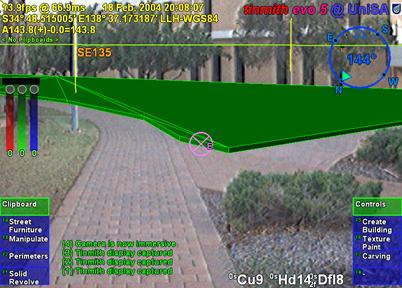
Figure 4‑3 AR view showing registration of perimeter to a physical
world grassy patch
|
4.2.2 Bread crumb trails
Using the previously defined street
furniture technique to place down prefabricated shapes is useful but limited to
objects created in advance. For large objects such as rivers, lakes, trails,
roads, and other ground features I have developed a technique named bread
crumbs. In many cases it is possible to walk near the edges of these ground
features, and so a direct system of marking out their vertices is realisable.
The bread crumbs technique is inspired by the children’s fairytale Hansel and
Gretel [GRIM22]. In this story, the children are
taken out into the forest by their parents in the hope they will not come back
home again. Hansel was carrying a loaf of bread however, and dropped small
crumbs of bread where they walked, enabling them to find their way back home
again. On the second occasion, the children found themselves unable to get home
because the birds in the forest ate up the trail.
|
Figure 4‑4 Example bread crumbs model extruded to form an unbounded
solid shape
|
With a mobile AR system, less edible and
more reliable virtual markers can be placed down on the ground to simulate
bread crumbs. The user walks along the perimeter of the object they wish to
model and manually specifies markers to place at points of interest under the
feet, as shown in Figure 4‑2. This is the same as marking waypoints when
using a hand-held GPS while walking. When the user fully walks around the
object, a closed perimeter is automatically formed and converted into polygons,
as in Figure 4‑3. While the initial perimeter defined is a thin polygon,
it can be infinitely extruded up to define a solid building outline, or
infinitely extruded down to approximate the bottom of a lake or river. The
resulting extruded object is unbounded in the vertical direction as shown in
Figure 4‑4, and must be completed using other techniques described later.
The bread crumbs technique has been used
to model roads, parking lots, grassy areas on campus, and other concave outline
style shapes. Paths and navigation routes may also be defined using bread
crumbs, except treated as a line segment instead of a solid polygon.
This section describes a series of
construction at a distance techniques based on the user’s physical presence in
the environment. Using simple head-based pointing, the geometry of planes
originating from the body can be specified, taking advantage of the user’s
sense of proprioception. Using CSG techniques, these planes can be used to
easily define solid building shapes out of arm’s reach. Since many buildings in
the physical world can be modelled using planes, the process of modelling can
be accelerated compared to the simplistic approach of creating each vertex and
edge manually.
4.3.1 Orientation infinite planes
|
Figure 4‑5 Infinite carving planes used to create a convex shape from
an infinite solid
|
Buildings in the physical world tend to
approximate collections of angled walls in most cases. As described in Chapter
2, a solid convex cube can be formed with the specification of six planes
arranged perpendicular to each other and a CSG intersection operator. Instead
of specifying these planes numerically, the user can create these same planes
in an AR environment by projecting them along the line of sight. By looking
along the plane of a wall of a building and aligning the two ends (a very
accurate method of positioning discussed previously) the user can project an
infinite plane along this wall (in a similar way to AR working planes). Each
plane defines a half space that when combined with a CSG intersect operation
will form a finite solid shape.
Figure 4‑5 depicts a five-sided
building and the location of the mobile AR user as they are sighting down each
of the walls, showing the infinite volume being iteratively bound by the
infinite planes. At the beginning of the operation, the AR system creates an
(approximately) infinite solid volume that will be used for carving. When the
user is aligned with a wall, they project an infinitely long vertical plane
along the view direction into the world. This plane divides the previous
infinite solid into two parts and the left or right portion (decided by the
user) is carved away from the solid and removed. As the user sights along each
wall, the solid will be reduced down to an object that is no longer infinite in
the X and Y axes. At completion, a floor is automatically created at ground
level, and the roof is left unbounded for carving using other techniques, since
it is impractical to sight along the roof of a very tall building. The final 3D
shape is stored using absolute world coordinates and reflects the geometry of
the physical building.
With this technique, the object can be
carved away iteratively and the user receives real-time feedback of the
infinite volume being bounded, allowing immediate undo in case of a mistake.
Compared to the direct methods described previously, this plane-based technique
allows the capture of buildings from a distance without having to actually
stand next to or on top of the building. Since the user is in direct control of
the modelling process, the positions of occluded surfaces can be estimated
using their knowledge of the environment. These features are useful because
many existing physical capture methods require a full view of the object, GPS
trackers do not work well near large buildings, and standing on top of a
building may not be possible or too dangerous. This technique is also much more
efficient than vertex and edge specification since each wall is handled with a
single primitive that is easy to create accurately. A limitation of this
technique is that using only planes and a CSG intersection to define objects
restricts usage to convex buildings with no indentations, and this will be
addressed further at the end of this section.
4.3.2 Position infinite planes
Another limitation of the orientation
infinite planes technique is the dependence on an orientation sensing device
for the head. While GPS units may have reliable accuracies in the order of 2
cm, orientation sensors vary in accuracy due to problems with interference and
limitations of the technology. These variations affect the placement of planes
in the environment and as the distance from the user increases, angular errors
cause increasing positional errors. The last section of this chapter will
further discuss the accuracy of these techniques in more detail, but using
techniques that can avoid the use of orientation sensing should be able to
produce much more accurate results.
|
Figure 4‑6 Orientation invariant planes generated using multiple
marker positions
|
In order to take advantage of the
stability of position tracking, the orientation infinite planes technique
described earlier can be modified to use two or more position points to specify
orientation, making it invariant to errors in orientation tracking devices.
Using the same landmark alignment concept discussed previously, the user can
accurately sight along a wall and mark a position. To indicate direction, the
user walks closer while maintaining their alignment and marks a second point.
These two points can then be used to project an infinite carving plane, with
Figure 4‑6 depicting the position markers and planes used to form a
complete building shape. By increasing the spacing of the marker points or
using a line of best fit amongst multiple points, the accuracy of this
technique can be further improved.
|
Figure 4‑7 Relationship between GPS accuracy and required distance to
achieve better than 1 degree of orientation error for two different GPS types
|
To measure the accuracy of this
technique, Figure 4‑7 depicts how the angular error is affected by the
positional error in the GPS and the distance between the two marker points. To
make this technique useful it must have an accuracy that is better than is
available using traditional orientation sensors. Assuming a maximum error of 1
degree, Figure 4‑7 contains the calculations to find the distance
required between markers for 50 cm and 2 cm accurate GPS units. Using the RTK
example, if 1.1 metres is required for less than 1 degree error then 10 or more
metres will produce orders of magnitude better results than previously
possible. For a 50 cm GPS these results are not so promising since the marker
distance required of 29 metres is quite large - the user will have to choose
between the errors introduced by the GPS or those from the orientation sensor.
4.3.3 Fixed infinite planes
|
Figure 4‑8 Orientation invariant planes formed using first specified
angle and markers
|
This technique is similar to the position
infinite planes technique in that it is invariant to orientation sensing
errors. The previous technique required the user to specify the orientation for
each plane by using two points, but if the angles at each corner are known to
be equal then only one orientation is needed and the others can be calculated
automatically. The user creates the first plane using the same method described
previously, but for each additional plane only one position marker is recorded.
Based on the number of positions marked, the system knows the number of walls
to create and calculates the orientation for each position point based on the
first plane. This technique uses nearly half the number of points and yet
produces the same accuracy if the first plane is properly placed and the
building meets the required properties. Figure 4‑8 depicts the markers
created by the user and how they are used to project planes through the
environment to form a solid shape.
4.3.4 CSG operations
Many objects in the world are not the
same shape as simple boxes, cylinders, spheres, and cones. While it may seem
that many objects are too complicated to model, they may usually be described
in terms of combinations of other objects. For example, the process of defining
a cube with a hole using vertices is time consuming, but can be easily specified
with a CSG operation. As discussed in the background chapter, CSG is a
technique commonly used by CAD systems, supporting Boolean set operations such
as inversion, union, intersection, and subtraction [REQU80]. The manufacture of objects in the
physical world is also performed in a similar manner - to produce the previous
example a drill is used to bore out a hole in a solid cube.
|
Figure 4‑9 Box objects can be moved into a building surface to carve
out windows
|
To demonstrate CSG operations outdoors,
Figure 4‑9 depicts an example where a user is applying the CSG difference
operator to subtract cubes from a building shape. This could be used when the
user needs to carve out indented windows. The first example shows a cube placed
at a distance (1a), and then dragged sideways until it enters the building
shape (2a). The second example shows a cube attached to a working plane (1b)
and then pushed (2b) into the surface of the building (similar to a cookie
cutter), requiring close access to the building. As the cube is being
positioned by the user, the CSG difference operator is interactively calculated
and displayed to the user.
The infinite planes examples previously
described have only dealt with convex shapes, limiting the types of buildings
that can be modelled. A convex shape can be simply described as one that
appears to have the same shape when a sheet of rubber is stretched over its
surface, such as the trapezoid in Figure 4‑10. A concave shape is more
complex and contains holes or other indentations that will not be visible when
a sheet of rubber is stretched over. Concave buildings similar to the T, L, and
O shapes in Figure 4‑10 cannot be modelled directly using a single set of
infinite planes because planes from one part of the object will exclude other
parts. Concave objects can be created using other convex objects as inputs
however, such as with the subtraction of one box from another depicted in
Figure 4‑11. The two boxes can be individually created using infinite
planes, and then combined using a CSG difference operator to produce a concave
object. When combined with CSG techniques, infinite planes become more useful
with the ability to also model concave objects.
|
Figure 4‑10 Convex trapezoid and concave T, L, and O-shaped objects
Figure 4‑11 Concave object created using CSG difference of two convex
boxes
|
This section describes a series of
construction at a distance techniques based on AR working planes. The previous
techniques are capable of placing prefabricated objects and capturing bounding
boxes for large objects, but detailed modelling is not provided. Using AR
working planes and a 2D input glove (as used in these examples), the user can
specify much more intricate details to create realistic 3D models.
4.4.1 Projection carving
The projection carving technique modifies
existing objects by projecting points against surfaces and then cutting away
extrusions to produce new highly concave shapes. This technique provides the
ability to construct features such as zig-zag roofs and holes that are
difficult or impossible to model using previously described techniques. Figure 4‑12
depicts an example of how this technique can be used to carve two peaked roofs
onto a building model. These building models may have been created using
infinite planes and projection carving can be used to restrict the infinite
roof to a finite volume. The AR working plane is created relative to a polygon
that has been selected by the user. The object that contains the polygon is
then used as the input for the upcoming carving operation. The user then
creates vertices along the surface of the AR working plane and these are
connected together to form a 2D concave outline. This outline is then extruded
along the surface normal of the working plane and used as an input tool for a
CSG difference carving operation.
|
Figure 4‑12 AR working planes are used to specify vertices and are
projected along the surface normal for carving the object’s roof
|
The projection is performed using
orthogonal extrusion from the AR working plane, and is position invariant so
points can be entered from any location in front of the polygon. This enables
the user to cut a flat roof on a 100 metre high building while standing at
ground level and looking up. If the cursor was directly used to carve the
object directly like a laser beam, the system would produce pyramid-shaped
extrusions. For some buildings, the user may only desire to create a flat roof
or a single slope, and by creating only one point the system will create a
horizontal cutting plane, and with two points a diagonal cutting plane is
created. More than two points implies the user wishes to cut with an outline
and so it must be fully specified as in Figure 4‑12. The CSG operation
can be switched from difference to intersect if desired, with the effect being
that the user can cut holes or split an object into separate parts instead of
carving the outside. Used in this form, orthogonal extrusion is limited to
carving operations that can be seen in a silhouette representation – other
features such as indentations that are not visible from the side can not be
captured with this technique. Some of these limitations can be overcome by
limiting the depth of the extrusion used for carving. By using a small fixed
value or controlling it by moving the body forward or backward, the extrusion
can be controlled by the user and used for features such as windows or doors.
This technique is first demonstrated with
a simple example of modelling a building with a sloped roof such as in Figure 4‑13.
The user first captures the overall geometry of the building using orientation
infinite planes with an unbounded roof. To carve the roof, the user positions
their body somewhere in front of the building so that the entire slope is
easily visible. The user then indicates with the cursor the first vertex
defining the roof on the left, then the peak of the roof, and then the right
side of the roof, as shown in Figure 4‑14. To complete the selection, the
user must enter vertices around the overall building to indicate that the rest
of the object should be kept. The selection region is then used to define a
carving tool that removes all objects outside the region, to produce the final
shapes shown in Figure 4‑13 and Figure 4‑15.
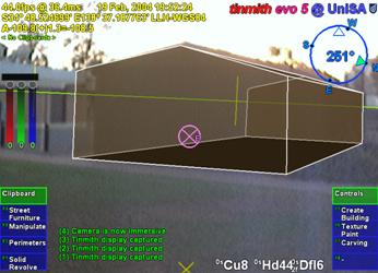
Figure 4‑13 AR view of infinite planes building created with sloped roof
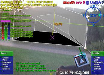
Figure 4‑14 AR view of infinite planes building being interactively carved
with a roof
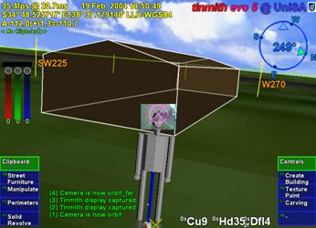
Figure 4‑15 VR view of building with sloped roof, showing overall geometry
A second example demonstrating this
technique is a small automobile being modelled outdoors in Figure 4‑16.
Firstly, a prefabricated box is created and scaled to approximate the overall
dimensions of the car. The user next views the car from the side and intersects
points against the box surface to define the silhouette. Figure 4‑16
shows the markers being placed on the box, and Figure 4‑17 shows the
final solid shape of the car approximately matching the physical world. The
object can then be carved along any other polygons to further refine the model
until it suits the user’s requirements.
|
1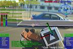 2 2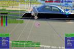 3 3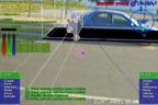 4 4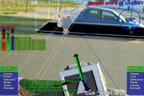
5 6 6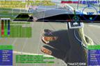 7 7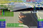 8 8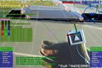
Figure 4‑16 Frames of automobile
carving, with markers placed at each corner
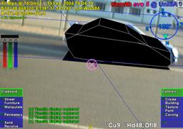 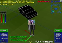
Figure 4‑17 Final resulting automobile shown overlaid in AR view, and in
a VR view
|
4.4.2 Projection colouring
Once a building has been created, the
user may desire to place windows, doors, and other extra details onto the
model. While it may be possible to draw these details onto a texture map (which
cannot be zoomed arbitrarily), or to place extra polygons outside the building
to represent these (covering the original building), the building model itself
remains untouched. If these new polygons are removed or manipulated, the
original solid object remains since the changes are only superficial. A more
desirable scenario is that polygons of a different colour are actually cut into
the subdivided surface of an object, so that if they are deleted it is possible
to see features inside the object that were previously concealed. I have named
this technique projection colouring and its operation is depicted in Figure 4‑18.
Using the same steps as projection carving, vertices are projected against an
AR working plane created relative to the surface and then connected into an
outline. Instead of carving away the outline, the surface is subdivided and the
colour of the outlined polygon is modified. The newly coloured polygons may
then be deleted or manipulated freely by the user if desired. The window and
door in Figure 4‑18 have been cut into the surface using this technique,
with the door then openable using a rotation.
|
Figure 4‑18 Schematic illustrating the painting of a window onto a wall
surface
|
4.4.3 Surface of revolution
|
Figure 4‑19 Examples showing surface of revolution points for tree and
cylinder objects
|
When working outdoors and modelling
natural features such as trees and artificial features such as fountains,
box-shaped objects are usually poor approximations to use. In an attempt to
model these objects, I have used surface of revolution techniques (as used in
many desktop CAD systems) to capture geometry that is rotated about an axis.
The user starts by creating an AR working plane in the environment, with the
most intuitive way being to sight toward the central trunk of the tree and
project the AR working plane along the view direction. The user then projects
vertices onto the AR working plane, defining one half of the outline of the
object. After specifying the vertices along the axis of rotation, the system
generates a solid object by rotating the outline around the axis, as depicted
in Figure 4‑19. Figure 4‑20 shows an example where the vertices of
a tree have been specified with a preview shape generated, with Figure 4‑21
showing the final shape in the environment. This technique generates good
results when modelling natural objects such as pine trees that are highly
symmetrical about the trunk. For trees that grow with deformities and other
non-symmetrical features this technique may not generate suitable
approximations. To improve the approximation, previously described carving
techniques may be applied to refine the model until the user is satisfied with
the object.
|
Figure 4‑20 AR view of surface of revolution tree with markers on AR
working plane
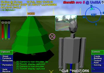
Figure 4‑21 VR view of final surface of revolution tree as a solid shape
|
4.4.4 Texture map capture
When implementing live AR video overlay,
the mobile computer includes a video camera that may also be used to supply
textures for polygons. By using the same tracking devices that are already
required for AR, the system can automatically match up images from the camera
to polygons in the scene. Captured models are normally only presented using a
single colour and texture maps increase the realism for users without having to
add extra polygons for detail. This texture map capturing technique is an
alternative to the previously described projection colouring technique when
only superficial details are required. To perform texture map capture, the user
stands at a location where the texture for an object’s polygon is clearly
visible to the camera. The user selects the polygon to activate capture mode
and the system projects the polygon vertices onto the AR video overlay to map
the still image as a texture. The user repeats this operation for each polygon
until the object is completely textured. An example is shown in Figure 4‑22,
where a stack of pallets is modelled using a 1 metre box and then textures are
captured for the polygons. The final resulting model is shown in Figure 4‑23.
|
Figure 4‑22 Outdoor stack of pallets approximating a box, before modelling
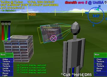
Figure 4‑23 VR view of final model with captured geometry and mapped
textures
|
The best results for this technique are
obtained when the object is fully visible and fills as much of the HMD as
possible, as well as being perpendicular to the user’s viewing direction. Since
OpenGL only supports linear texture mapping, if the angle to the polygon is
large (such as the roof of the box in Figure 4‑22 and Figure 4‑23),
the texture will be highly distorted since a non-linear mapping is required.
Although techniques for capturing textures of 3D models have been described
previously, this has not been performed in a mobile outdoor AR environment.
Previously discussed work by Debevec et al. implemented the capture of 3D
models from photographs and extracted textures for each facet [DEBE96]. Lee et al. also implemented the
capture of textures in AR but with surfaces being modelled within arm’s reach
using a wand, with the system automatically capturing textures when video
frames were deemed suitable [LEE01]. The video stream used with mobile
AR suffers from problems with motion blur and tracker registration, and having
the user choose the moment to capture the texture generates the highest quality
output.
4.5 Integrated
example
While a number of techniques can perform
the modelling of simple and useful shapes, the true power of construction at a
distance is expressed when used in combinations. This integrated example is
designed to highlight all of the features of the described modelling techniques
with the construction of an abstract building in an outdoor environment. The
user walks outside to an empty piece of land and creates a landscape that they
would like to preview and perhaps construct in the future. As an added feature,
this model may be viewed on an indoor workstation either in real-time during
construction or at a later time. Some other similar applications are for
creative purposes such as an abstract art or landscape gardening design tool.
Figure 4‑24 and Figure 4‑25
show different views of this example at the end of the construction process.
The first step is to create the perimeter of the building shape using the bread
crumbs technique - the user walks around the building site and places down
markers at the desired ground locations, forming a flat outline. Next, the
outline is extruded upwards into a solid 3D shape. Using projection carving,
the user cuts a main roof to make the object finite and then carves a slope
using various control points. After the overall roof structure is created, the
object is lifted into the air. At this point, the supporting columns, trees,
tables, and avatar people are created using street furniture placement of
prefabricated models at the desired locations. The building is then lowered by
visual inspection onto the supporting columns. Next, the user performs further
carving and a large hole is created through the centre of the building.
Projection carving is then used to cut out two large sections of the building,
causing it to exist as three unattached solid shapes most visible in Figure 4‑24.
After around 10 minutes for this example, the desired model is complete and the
user can now move around the environment to preview it from different view
points.
|
Figure 4‑24 AR view of final abstract model, including street furniture
items

Figure 4‑25 VR view of final abstract model, including street furniture
items
|
The construction at a distance techniques
rely on the position and orientation sensors for all tracking, and so increasing
the accuracy of these devices will produce improved results and affect the
minimum model size that can be properly captured. Errors from each sensor have
different effects on the captured models since one is measured as a distance
and the other as an angle. When rendering the AR display, results are also
affected not only by the errors in the current tracker data, but also those
from the capture process. Tracking devices affect the overall operation of the
system and how it can be deployed in the physical world.
The position sensor used in these
examples is a Trimble Ag132 GPS, with an accuracy of approximately 50
centimetres and working reliably amongst small buildings and light tree cover.
To ensure the most accurate positioning possible, an indicator on the HMD shows
the quality of the GPS signal to the user. For orientation, an InterSense
IS-300 hybrid magnetic and inertial sensor is used, although the tracking is
unreliable when there are magnetic distortions present in the environment or when
the user is moving quickly and disturbing the sensor. Since the accuracy of the
IS-300 may vary unpredictably, this is the most critical component in terms of
reliability and accuracy.
When modelling a new object, the accuracy
of projection-based techniques is dependant on the user’s current location and
the direction they are looking. For the highest accuracy, it is desirable to be
as close to the object as possible, minimising the distance the projection can
stray from the desired direction caused by angular errors in the orientation
sensor. When viewing an existing virtual object, the registration errors with
the physical world caused by the GPS will be the most accurate when viewed from
a distance due to perspective, while standing very close to an object will
cause these errors to be more noticeable. For registration errors caused by the
IS-300, these remain constant on the display at all distances due to their
angular nature.
While GPS is fast and reliable (with
accuracies of RTK GPS units at 2 cm in ideal conditions), improvements in
orientation sensing technology are required to make the construction at a
distance techniques more accurate. While the IS-300 is one of the best
mid-range priced trackers on the market, it is still not completely adequate for
modelling outdoors. Due to its use of magnetic sensors, distortion caused by
sources of magnetic interference such as the backpack, underground pipes, and
street lamps affect the accuracy of the tracking. To correct for this, the
backpack contains a touch pad mouse attached to the user’s chest to apply a
correction offset. The touchpad allows the user to fine tune the calibration
while moving outdoors through varying magnetic fields. I am currently
investigating methods of automating this calibration, with methods such as
optical natural feature tracking holding promise, but these are still current
research problems.
This chapter has presented my novel
construction at a distance techniques, designed to support the capture and
creation of 3D models in outdoor environments using AR. Construction at a
distance takes advantage of the presence of the user’s body, AR working planes,
landmark alignment, CSG operations, and iterative refinement to perform
modelling tasks with mobile AR systems. The techniques described in this
chapter include street furniture, bread crumbs, three types of infinite planes,
CSG operations, projection carving, projection colouring, surface of
revolution, and texture map capture. When used in an AR environment, users can
capture the geometry of objects that are orders of magnitude larger than
themselves without breaking AR registration or having to touch the object
directly. These modelling techniques are intuitive and support iterative
refinement for detail in areas that require it, with AR providing real-time
feedback to the user. While existing techniques are available for the capture
of physical world objects, these still have limitations and also cannot be used
to create models that do not physically exist. The construction at a distance
techniques were field tested using a number of examples to show how they may be
applied to real world problems. By discussing insights gained from these
examples I have identified areas for improvement that currently cause accuracy
problems.
5
"Research is what I'm doing when I
don't know what I'm doing."
Wernher Von Braun (1912-1977)
This chapter presents new user interface
technology that I have designed and developed for use with mobile outdoor AR
systems. This user interface is used to control the previously described AR
working planes and construction at a distance techniques, and is implemented in
a mobile outdoor AR modelling application named Tinmith-Metro. The
implementation of the techniques described in this dissertation demonstrates
their use, and allows different ideas to be tested and iteratively refined
through user feedback. Testing the techniques out in the field has also given
insights into more efficient methods after experimenting with early prototypes.
The user interface described in this chapter is designed to be implemented
within the limitations of current technology while still being intuitive to
use. The solution developed uses a pair of vision tracked pinch gloves that
interact with a new menuing system, designed to provide a cursor for AR working
planes and command entry to switch between different operations. The user
requires feedback on the HMD while using the system, and so the design of the
display with its various on screen objects is discussed. To implement the full
Tinmith-Metro application, a large hierarchy of commands was created to control
the various modelling techniques and these are presented in a format similar to
a user manual. This chapter ends with a summary of a number of informal user
evaluations that were used to iteratively refine the interface.
Augmented and virtual reality both use
the motion of the body to control the image that is displayed to the user.
While tracking the body is critical to rendering AR and VR displays, fine
grained manipulation and selection operations typically require the hands to
intuitively specify. The previously described Smart Scene [MULT01] and CHIMP [MINE96] applications have intuitive user
interfaces that involve the use of hand gestures supplied by high quality
tracking systems. These user interfaces implement many best practice techniques
for direct manipulation in VR that are desirable for modelling tasks. While
outdoor AR is similar and using these techniques is desirable, there are a
number of unique problems (discussed in Chapter 2) that require solutions.
Previously discussed outdoor AR systems use indirect style user interfaces
involving tablets, keyboards, joysticks, trackballs, gyro mice, and other
hand-held devices but do not support direct manipulation operations. The user
instead steers a cursor across the display using indirect motions of the hands.
Some devices such as velocity-based inputs have a further level of indirection
and so are even less intuitive to use. Shneiderman [SHNE83] and Johnson et al. [JOHN89] both discuss how adding levels of
indirection may make user interfaces less intuitive to operate. Furthermore,
any AR user interface developed must use mobile technology so the user may roam
freely in the outside environment. It must take into account restrictions on
size, performance, electric power consumption, and weight.
I was initially inspired by the elegant
combination of commands and pointing implemented by Bolt in the Put-That-There
system [BOLT80]. The user is able to point their
hand toward objects projected onto the walls and then speak commands to perform
operations. The use of menus by many other applications is an unintuitive
abstraction that forces users to select suitable options from a list, usually
with the same input device. The direct command entry in Put-That-There is
similar to how people operate in the real world, and can be observed when
watching a supervisor explain an operation to a worker: “Pick up that brick and
place it over there”, while at the same time pointing with the hands to
indicate exactly what object and where to put it. Brooks also agrees and
discusses how commands and operations should be separated in interactive systems
[BROO88].
Based on this initial inspiration from
Bolt and Brooks, I have developed a user interface involving the use of tracked
gloves so the user can point at objects and interact with them in a mobile outdoor
AR system. Since the user is wearing gloves, there is no need for any other
devices and the hands are free to perform physical world tasks. Implemented
using vision tracking, the interface can locate the user’s hands in the field
of view. Using optical methods (discussed further in Chapter 7) is one of the
only ways to perform tracking of the hands outside, although the 3D accuracy is
quite poor compared to indoor magnetic tracking. One property of the optical
tracker is that its 2D accuracy is quite good, and 2D cursors can be calculated
from the hand positions very easily. These 2D cursors are suitable for input to
the AR working planes techniques and used to perform interactions in 3D
environments. Due to poor distance and orientation detection, these values are
not used to control the user interface. The use of tracked gloves to perform
selection and manipulation of objects is a very direct user interface because
natural hand gestures are used to express actions. Although the object at a
distance is not being touched directly, humans still intuitively understand
this operation. When talking with others, humans naturally point and understand
these gestures even when the object is very far away. Pierce et al.
demonstrated a number of simple selection techniques demonstrating this using
image planes [PIER97].
Brooks suggested that commands and
operations should be kept separate and so I have included this important idea
into the user interface. Many systems implementing direct manipulation also
make use of menus or other widgets that the user must reach out and grab. These
systems use the same cursors for both interaction and command entry, and these
ideas do not work well when implemented with poor tracking. Rather than having
unreliable command entry caused by poor tracking, I have developed an interface
based on the pinching of fingers to select commands from menus fixed to the
display. The pinching of fingers is a very reliable input that is easy to
implement in any environment, and allows the hands to be outside the field of
view and untracked during command entry. The use of finger pinches mapped
directly to the menu also allows the same hand to perform simultaneous
interaction and command entry.
By separating the command interface from
pointing, Brooks describes how the command input method can be changed without
affecting interaction. He also suggests that speech recognition is a natural
candidate for command selection, as used by Bolt in Put-That-There. Johnson et
al. also point out that the use of command interfaces such as speech input
encourages the user to think of the computer as an assistant or co-worker
rather than a tool [JOHN89]. While it would be interesting to
explore the use of speech recognition for command entry, the current software
available to implement it is very CPU intensive. When using a mobile computer
there are limited resources available, and speech recognition would prevent the
rest of the AR system from functioning adequately. Problems such as lack of
accuracy and interference from noise (especially when outside) were common in
older systems, and although improvements have been made they have not been
eliminated. Currently this user interface does not implement speech
recognition, but is designed to support this and is discussed as a future area
of research at the end of this chapter.
The user interface is made up of three
components: a pointer based on the tracking of the thumbs with a set of gloves
worn by the user; command entry system where the user’s fingers interact with a
menu for performing actions; and an AR display that presents information back
to the user. The display for the interface is fixed to the HMD’s screen and
presents up to ten possible commands as menu options at any one time. Eight of
these commands are mapped to the fingers as depicted in Figure 5‑1, and
the user activates a command by pressing the appropriate finger against the
thumb. When an option is selected, the menu refreshes with the next set of
options that are available. Ok and cancel operations are activated by pressing
the fingers into the palm of the appropriate hand and are indicated in the
topmost boxes of the menu. The interaction cursors are specified using fiducial
markers placed on the tips of the thumbs, as shown in Figure 5‑2. With
this user interface, the user can perform AR working planes, action at a
distance, and construction at a distance techniques in mobile outdoor AR environments.
|
Figure 5‑1 Each finger maps to a displayed menu option, the user
selects one by pressing the appropriate finger against the thumb
|
The concept of AR working planes and two
example uses were presented in Chapter 3, one for the manipulation of objects
and the other for the creation of new vertices. AR working planes are designed
to support interactions at large distances and only 2D input is required,
simplifying the tracking requirements. Using the previously mentioned gloves,
fiducial markers are placed on the thumbs to provide 3D tracking information
using the ARToolKit [KATO99]. Due to the implementation of
ARToolKit, the 6DOF accuracy can be quite poor but overlaid objects always
appear to register with the targets. When the 3D coordinates from the tracker
are projected onto the image plane of the display, an accurate 2D cursor can be
obtained, as displayed in Figure 5‑2. With the availability of suitable
tracking, the user interface contains cursors for both hands as well as a head
cursor fixed to the centre of the HMD. Each operation is implemented using
varying combinations of these input cursors depending on what is most
appropriate. This section describes the implementation of one, two, and
zero-handed AR working planes techniques with examples demonstrating their use
outdoors.
|
Figure 5‑2 Immersive AR view, showing gloves and fiducial markers,
with overlaid modelling cursor for selection, manipulation, and creation
|
To simplify manipulation tasks for the
user, operations such as translate, rotate, and scale are implemented using
separate commands. This is on the assumption that the user will wish to work
with certain degrees of freedom without affecting others. Researchers such as
Hinckley [HINC94a] and Masliah and Milgram [MASL00] have demonstrated that users have
difficulty controlling both the position and orientation of the hands at the
same time. Constrained manipulation is also useful when poor tracking is used,
so that other degrees of freedom are not affected when simple changes are made.
Manipulation handles (as used in many previous 2D and 3D systems) are not used
since they would be difficult to grab with the poor tracking available. The
user instead activates the desired manipulation operation with a menu command
and may grab any visible part of the object. This is also more intuitive since
objects in the physical world can be moved by grabbing any part of the object.
5.2.1 One-handed interaction
Users may perform selection operations
using a single hand controlling the 2D cursor. The cursor is projected into the
environment and intersected against the nearest object, similar to the image
plane techniques described by Pierce et al. [PIER97]. The object closest to the user
will be selected, placed into a selection buffer, and rendered transparently in
a selection colour for user feedback. Since the most common operations
performed by users only involve single objects, the implementation has been
streamlined so that selection is automatically performed when a manipulation
command is activated.
To operate on many objects
simultaneously, the user can select several objects and collect them together
into a selection buffer. When a manipulation task is then specified by the
user, they may select any object that is a part of the collection and then all
objects will be used as inputs. The ability to collect objects together is also
useful for specifying operations such as CSG where two inputs are required and
both may contain multiple objects. Multiple objects are currently collected together
by selecting each object, although other techniques such as two-handed rubber
banding are simple to implement if required. To support modelling, an arbitrary
number of selection buffers may be stored in a circular list for later use.
Overall then, a modelling session may have a number of selection buffers (with
one being active), and each buffer contains collections of objects that must
all be operated on together. Selection buffers are similar to groups used in
drawing editors, except no changes to the scene graph are made to express this
relationship. Each selection buffer is represented using a different
transparent colour to assist the user with identifying groupings. The active
selection buffer may be nominated by cycling through the available list or
selecting an object that is part of the desired selection buffer. Within a
selection buffer, references to objects are also stored in a circular list,
with one object nominated as the last object. When a new object is added
to the selection buffer it will become the new last object, and extra commands
are provided to operate on only the last object instead of the entire selection
buffer. The last object pointer is useful for performing a type of undo to
allow objects to be deleted in the order of creation.
Direct manipulation-based translation
operations may be performed by the user with a single hand. At the start of the
operation, the user selects an object (and automatically any other sibling
objects which are part of the same selection buffer, if any) and an AR working
plane is created using head-relative coordinates with normal pointing toward
the user, located at the point of intersection with the object. As the user’s
hand moves, the cursor is continuously projected onto the AR working plane and
used to offset the object accordingly, performing translation and maintaining
the same object to user distance. If the user moves their body during the
translation operation then the object will be moved in the same direction as
this motion. If the user changes their head direction then the object will
rotate around with the user’s head. Figure 5‑3 shows an animation of a
typical translation operation with a virtual tree being directly manipulated
across the landscape by the user’s hand and head motion. Instead of using
head-relative coordinates, the AR working plane could also be defined in world,
location, or body-relative coordinates to support different motion constraints.
The properties of AR working planes relative to these different coordinate
systems were described previously in Chapter 3.
Using AR working planes, the hand tracker
and 2D cursor may also be used to project 3D vertices. Chapter 4 described a
number of techniques involving the placement of vertices for the carving of
objects and creating surfaces of revolution. When these techniques are
activated, an appropriate AR working plane is created and the user can place
vertices onto the plane using finger pinch commands.
5.2.2 Two-handed interaction
The AR working planes scale and rotate
operations require more inputs than the translation operation because an axis
to scale or rotate about must be defined along with the adjustment vector.
Scale and rotate may be performed more naturally through the use of two-handed
input, which has been shown to improve performance and accuracy for users.
Two-handed input techniques were first pioneered by Buxton and Myers in a study
using 2D environments [BUXT86], and then discussed in terms of 3D
environments in a survey paper by Hinckley et al. [HINC94a]. Sachs et al. found that using a
tracked tablet in one hand and a pen in the other was more natural than having
a fixed tablet and one-handed input [SACH91]. Zeleznik et al. presented some
two-handed 3D input methods for desktop applications, of which some are
implemented here [ZELE97]. These previous works all
demonstrate that by using the non-dominant hand as an anchor, the dominant hand
can accurately specify operations relative to this. Scaling may be performed by
stretching the object with the two hands. Instead of using the orientation of
the hand, rotation may be performed by using the angle between the two hands.
Scaling operations are initiated by
selecting an object and any associated selection buffer sibling objects with
the non-dominant hand, and an AR working plane is created at the object in
head-relative coordinates. Since the operation begins immediately after the
scale command is issued, the non-dominant hand must be selecting the object and
the dominant hand should be in a suitable position to specify the new relative
scale adjustment. Similar to translation, the AR working plane could also be
expressed in other coordinate systems to support different scaling constraints.
The AR working plane is then used to capture initial 3D coordinates for the
input cursors so that any relative changes can be applied to the object
selected. Since the scale operation is performed against an AR working plane,
only the two dimensions perpendicular to the surface normal of the AR working
plane may be adjusted. This implementation uses the head cursor as the scaling
axis and relative changes in the distance between the hands to control the
scaling factor applied. Figure 5‑4 shows an animation using a sequence of
frames with a tree being scaled about the head cursor using both hands. Scaling
about the head cursor was implemented because I did not want the scaling axis
to vary as both hands are being stretched apart. An alternative implementation
is where the object is grabbed by the non-dominant hand to specify the scaling
axis, and the dominant hand specifies a relative scaling adjustment to apply.
If the non-dominant hand moves during the operation then the object may either
move with the hand or remain still while the scaling axis moves instead.
Performing simultaneous translation and scaling on an object may be undesirable
because it is too many degrees of freedom to control with relatively inaccurate
tracking.
Rotation operations are performed using
similar two-handed input techniques as scaling, and started by selecting an
object and any associated selection buffer sibling objects with the
non-dominant hand. Similar to the previous scaling operation, the non-dominant
and dominant hands must be in the desired positions because the rotation
operation begins when the rotate command is selected. An AR working plane
relative to the head is created at the object (similar to translation and
scaling) and the initial 3D coordinates of the input cursors are captured.
Since rotation is performed against an AR working plane, the rotation is fixed
to occur on an axis parallel to the surface normal of the AR working plane. The
head cursor is used as the axis of rotation and the angle between the hands is
used to apply a relative rotation to the selected objects. Using two-handed
rotation has an added advantage of performing well with tracking systems that
produce high quality position but poor quality rotation values. By ignoring the
orientation values and using only the positions for rotation, I avoid these
errors and maximise the accuracy of the tracking system in use. Figure 5‑5
shows an animation using a sequence of frames with a tree being rotated about
the head cursor using two-handed input. Similar to scaling, an alternative
implementation is where the non-dominant hand grabs the object at the desired
rotation axis while the dominant hand rotates the object. If the non-dominant
hand moves then the object will move or the axis of rotation will move, and
this may be an undesirable number of degrees of freedom to control.
5.2.3 Zero-handed interaction
Since the user interface has very
powerful command entry which is not based on the cursor inputs, a number of
manipulation and creation operations are possible without requiring the hands
to be visible. The nudge operation allows the user to perform precise
manipulations based on fixed increments. The head cursor can be used similar to
the hands by pointing with a cursor fixed to the centre of the display.
To perform accurate translation, scale,
and rotate commands, an operation named nudging is provided to operate in fixed
increments and without requiring vision tracking. Nudging is based on the use
of arrow keys or other discrete controls for interaction which are commonly
used in 2D desktop-based modelling systems. The nudge move operation is used to
offset the object in one metre increments in any direction relative to the user
(left, right, up, down, towards, and away) and is useful in cases where the
distance is known exactly or the user cannot walk to drag the object. Scaling
is performed similarly using fixed units in any of the three axis directions or
with the axes linked together to ensure uniform scaling. Rotation implements
fixed angular offsets and can rotate about any of the three axes individually.
The scale and rotate nudge operations also provide the ability to scale away
from the user or rotate around the ground plane normal, which cannot be
performed normally since AR working planes flattens these directions. Nudging
does not require any input device tracking at all, and so is useful when
objects are too far to judge adjustments, or when tracking is of extremely poor
quality.
While the head cursor can be used to
perform translation operations similar to those implemented using the hands,
the main use is for the placement of objects in the world. AR working planes
and orientation infinite planes may be projected from the head into the
environment, and the head cursor is used to define the direction from the user
that this plane will follow. Using the head cursor is an obvious way to project
planes since the user is already aligning objects by sighting along the head
cursor cross in the centre of the display. The placement of street furniture
objects is also performed relative to the head cursor, with the objects being
placed either with zero distance at the user’s feet, or at a distance in front
of the user and placed in the direction of the head cursor. The head cursor is
further used to define surface normals for head-relative AR working planes
definitions, with the normal being calculated using the location of the user’s
eye and the virtual head cursor in the centre of the display.
The cursor can be used to perform a range
of powerful interaction operations, but a method of specifying which operation
to perform is required to support complex applications. This section describes
the hierarchical menu system I have developed to support a large number of
commands. As previously mentioned, finger pinches on the gloves are utilised to
control the menu system, allowing the user to select other menus and specify
commands. Since no tracking is required the user can hold their hands anywhere
they desire, and there is no need to dock the cursor onto menu options for
selection. This especially increases the speed of command entry under poor
tracking conditions. A menu-based system was chosen as a simple way of grouping
common tasks to reduce searching time and form the basis for a command entry
system. Having a logical and efficient layout of menu options is also critical to
making it intuitive for users. This section compares the design of the menu
system against a number of other relevant AR and VR command entry systems to
demonstrate its novel features.
5.3.1 Menu design
This dissertation has presented the
benefits of using hand pointing for interaction and so a menu design that is
compatible with this style of input is required. Using another 2D input device
would be cumbersome and force the user to switch between different input
methodologies. Therefore the design of the menu system is not based on the
traditional WIMP 2D style interface with selection of objects using a cursor.
Instead, the design is closer to that of the original MicroPro WordStar
application shown in Figure 5‑6 and used in the 1970s and 1980s [XTRE03]. This application uses a menu bar
along the bottom of the display to show the commands that are mapped to the
F1-F10 keys on the keyboard. To select a menu option, the user presses the
appropriate F-key and either the command is performed or the menu moves into a
sub-level of extra options. Before the introduction of the mouse to user
interface design, menu design was quite common and is discussed by Shneiderman [SHNE92]. Interacting with menus of this
type requires a discrete number of inputs and the user can directly select what
they want without having to control a dynamic input device.
|
Figure 5‑6 Original WordStar application, showing menu toolbar at
bottom of screen
(Image
courtesy of Mathias Winkler - XTree Fan Page)
|
The command entry interface I have
designed uses the fingers of the glove to select the desired menu node from a
set of vertical menu strips placed on the sides of the display. Figure 5‑1
depicts how each finger on the glove uniquely maps from top to bottom onto the
lower four coloured boxes forming the menu display. Transparency is used to
allow the user to see the physical world through the menu, reducing visual
clutter. The vertical placement of the menu strips intentionally matches the
orientation of the hands when held comfortably at rest and when performing
cursor operations. The direct mapping of finger pinches to menu options helps
the user to quickly select the correct menu node. In addition to the user’s
eight fingers available for selection, two extra menu items located on top of
the existing list are activated by pressing the fingers onto the palm and
indicate major operations such as ok and cancel. The menu display is always
fixed to the screen of the HMD and is ready to perform command entry regardless
of the view direction or the position of the hands.
When the user selects a menu option, the
system indicates the item by colouring it red, and then on release an audible
tone is given. Menu nodes can execute internal commands, move to a deeper level
in the menu, or both, and after performing these actions the display is updated
with the newly available options. When a task is completed or cancelled, the
menu returns back to the top-level node to perform the next operation. An added
feature from the development process is that the menu can also be controlled
using a traditional keyboard similar to the WordStar interface described
earlier. This is useful for debugging when working indoors and for externally
helping out a troubled user during a demonstration.
The command entry system has a task
oriented nature, which is customised towards a particular set of operations
that are being performed. When a user enters a mode such as carving, the menu
does not return to the top-level but instead remains at the carving menu.
Various carving operations are then available with only a single press required
to activate them. At the completion of the carving task with the ok palm
gesture, the menu returns back to the top-level so the user can select another
task. The alternative is that the user has to navigate through many levels of a
menu for each step in a task, which is highly inefficient. Each task is
represented using a node in the hierarchy, with each step stored as a child of
the parent task. When performing a particular task, only steps that are
relevant at that time are presented to the user, reducing clutter. Section 5.5
describes the layout of the Tinmith-Metro menu tree, demonstrating how the
commands are arranged to support a complex modelling application. This
hierarchy has been optimised to ensure that commonly performed tasks are easily
accessible to the user.
5.3.2 Related work
There has been a large body of previous
work in the area of command entry for both VR environments and wearable
computers, some of which is possible to leverage for use in mobile outdoor AR.
This subsection compares some of the most relevant existing work against the
user interface described in this chapter.
As previously described, Bowman and
Wingrave have developed a VR menu system that also uses pinch gloves as an
input device [BOWM01]. The top-level menu items are
mapped to the fingers on one hand and the second-level options to the fingers
on the other hand. Using the small finger, the user can cycle through extra
options if more than three are available. This technique is limited to a depth
of two due to its design and does not scale easily to a large number of
commands. While Bowman and Wingrave’s use of finger mapping is similar to my
approach, my method (first described in [PIEK01b]) is superior because it allows a
larger number of commands and minimises the number of presses required to
perform the desired task.
In the outdoor AR domain, the original
Touring Machine work by Feiner et al. utilised a small tablet computer with a
web browser interface to control the main system [FEIN97]. Other research with tablets is
also performed in the Studierstube environment by Szalavari and Gervautz [SZAL97] and extended later by Schmalstieg
et al. [SCHM00] and Reitmayr and Schmalstieg [REIT01a]. Both of these user interfaces are
useable while mobile because the tablets are compact devices that can be held
in the hands. The disadvantage of these interfaces is they are not hands free,
and require the tablet to be the centre of the user’s attention to operate.
Using the tablet to manipulate objects in the 3D view is also a less direct
form of interaction and requires the user to divide their attention between the
3D view and the tablet.
The N-fingers technique was created by
Lehikoinen and Roykkee for mobile outdoor navigation and context awareness
using AR cues [LEHI01]. N-fingers uses gloves with
metallic contacts similar to pinch gloves, except the contacts are arranged in
a diamond shape in the middle of the fingers. This technique is primarily
designed for scrolling through menus and lists, since the diamond shape maps
easily to a set of directional arrows. By mapping the fingers to scrolling
directions, the user can work with large lists of items but this also prevents
jumping directly to desired options in one press. Since N-fingers can only be
used for command entry, it requires another input technique to provide 3D
interaction.
Blasko and Feiner present the use of a
touchpad mouse for controlling a menu [BLAS02]. Instead of using the touchpad to control
a relative mouse cursor, this interface uses the absolute position of the
fingers to select from menu options. Menu options are directly selectable and
so the user does not need to track the motion of a cursor or look at the hands,
making it ideal for wearable applications. With the number of menu options
limited by the user’s four fingers and the resolution of the touchpad, menu
hierarchies are used to extend the number of options that can be provided.
Since the fingers must press against the touchpad surface mounted on the body,
the user cannot perform cursor manipulation with the same hand as command
selection.
The SKETCH system by Zeleznik et al. uses
a gesture-based interface controlled by a 2D mouse to draw 3D pictures [ZELE96]. Hand gestures are analysed to
initiate various commands such as selection, manipulation, and deletion. As
previously discussed, gesture-based input requires the use of fast and accurate
tracking to capture the motions correctly. There are also limits to the number
of hand motions that can intuitively map to commands, with the rest requiring
the user to memorise them. With the availability of limited outdoor tracking
and a large number of abstract modelling concepts, higher-level approaches such
as menus were chosen for the user interface.
The user interface provides a wide range
of information to the user apart from just cursors and menus. Useable AR
applications require other status information so that the user understands the
state of the application and the environment around them. This section
describes the display features that are used in the Tinmith-Metro mobile AR
modelling application.
5.4.1 Screen overlay
When viewing virtual objects outdoors, a
3D view registered with the physical world using tracking devices is required
for the AR overlay. This overlay contains virtual objects such as buildings and
trees that appear to exist in the physical world. The renderer also embeds
other information into this view to improve the user’s situational awareness.
Shadows are rendered underneath objects to indicate their height relative to
the ground plane. A 10 metre by 10 metre grid with a 100 square metre size is
overlaid on the ground plane to indicate how far objects are away from the
user. Tick marks with labels are placed every 15 degrees onto the horizon to
indicate directions and provide steering cues.
Other 2D information is fixed to the HMD
using screen-relative coordinates and is overlaid on top of the 3D view. 2D
information is used to indicate the status of the system to the user and can be
selectively turned on an off. Figure 5‑7 depicts the placement of the
various display components described below:
· Menus - As discussed previously, the
green and blue boxes in the bottom left and right corners of the display are
used to indicate the currently available menu options.
Notice
list - In green text between the menus is a four
line long message area, where the system indicates errors and other events as
they occur.
Tracker
status - At the bottom are status strings for the
head, hand, and body tracking devices. The small number superscripted to the
left is the number of seconds since the last update. For the hand tracker (Cu)
and the head tracker (Hd), the number to the right indicates the rate per
second that the updates are arriving. The GPS uses a different notation where
the letter X is used to indicate no GPS coverage, G for normal GPS reception,
and D for high quality differential reception, followed by the number of
satellites being tracked.
|
Figure 5‑7 Immersive AR overlay display components explained
|
· Heading indicator - At the top right is
a blue circle used to indicate the current heading of the user’s view. The
outlined triangle indicates the direction the user is facing, and the solid
green triangle indicates the direction of geographic north. The NSEW labels
rotate around the circle as the heading varies.
Project
name - The top right contains the string
“Tinmith-evo5 @ UniSA” with a small university logo. This is used to identify
the software in demonstration videos and pictures.
Debugging - The top left contains the current frame rate and delay estimate,
a clock showing the current date and time, and a display of the current
position of the user.
Clipboard
list - Each clipboard is represented as a string
with an id number and colour value used for objects that are part of the
clipboard. The names of objects contained within are listed underneath the
clipboard name.
Colour
selector - The cursors can be moved through an
invisible cube in the view frustum where XYZ directions map to RGB values on a
colour cube. The slider bars indicate the contribution of each colour and above
this is a small rectangle showing the final colour. This colour can be applied
to the surfaces of objects being modelled.
Cursor
overlays - The vision tracking system produces 3D
output that is used to overlay a 3D axis object onto each marker. This axis
object is then flattened against the display and used to produce 2D cursors
that may then be used with AR working planes. A 2D head cursor is fixed to the
centre of the display representing the direction that the user is looking. An
optional trackball mouse may be used for debugging to provide a cursor instead
of the gloves.
5.4.2 VR camera views
|
Figure 5‑8 Top down aerial view of VR environment in heading up and
north up mode
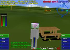 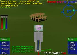
Figure 5‑9 Orbital view centred on the user with a VR style display
|
AR is designed to overlay virtual objects
onto the user’s view of the world and is intuitive to use since it is
experienced similar to the physical world. This view may cause problems in
situations where very large objects such as buildings may exceed the field of
view of the display, objects may be too distant to clearly view, or other
objects may be occluding an object of interest. The immersive view restricts
the user if it is impractical or impossible for the user to move to a new
viewing position. In these cases, it is more useful to work in an external VR
style view (such as orbital view by Chung [CHUN92] and Koller et al. [KOLL96]) where the user sees a view of the
virtual world from an external perspective. The advantages of external views
are also discussed by Brooks, who mentions that users find a local map of the
world useful to show where they are, what they are looking at, and to build a
mental model for navigation [BROO88]. In the external views I have
implemented, the ground and sky are both rendered using texture maps so that
the user understands they are looking at a fully virtual view and are no longer
immersive. Since the external view is designed to be used while wearing the HMD
outdoors, the body of the user is shown in the centre of the display and motion
about the physical world is updated in real-time. Top down views such as that
shown in Figure 5‑8 provide an aerial perspective of the area, with north
up mode being fixed while heading up mode rotates the map in the direction the
user is looking. Orbital views such as that shown in Figure 5‑9 link all
3DOFs of head rotation to orbiting motions at a fixed distance around the user.
Other views such as that shown in Figure 5‑12 are fixed relative to the
body location so that it is not affected by rotation. These external views are
generally only used while stationary because the physical world is completely
blocked out and the user may not be able to safely move. The user is able to
adjust the camera view using body position or head rotation (as discussed
previously) but not hand gestures, and can freely switch between immersive and
a number of pre-programmed external views using menu commands.
5.4.3 Video overlay
The simplest form of AR is
optically-based, where the system only draws in the AR detail with the rest of
the display remaining black for the physical world to be viewed in the HMD. In
order to improve accuracy and achieve higher quality images, my implementations
have switched from using optical overlay to video overlay (both of which are
described in Chapter 2). All of the pictures presented in this dissertation of
the final working system were captured using video AR. Performing video overlay
is more complicated than in the optical case, and the computer needs to capture
the video from a head mounted camera, render this to the display, and then
overlay the 3D and 2D graphics on top to produce the final output for the HMD.
The implementation still contains the ability to switch to optical overlay, but
this is rarely used.
While this section does not discuss the
overall software implementation, the renderer is implemented using OpenGL. The
fastest method of rendering video frames is to draw a polygon of the desired
shape and map the video frame as a texture map. When the texture map is
rendered, it must be placed behind all the other objects in the scene, and so
must be at a large enough distance away from the user. To fill the entire view
of the user, the polygon must be attached to the user’s head and scaled to
exactly fit the entire field of view. By default this video texture plane is
placed at the focal point of the HMD (usually located at 1-2 metres from the
user) and then scaled out to a large distance. Scaling relative to the head
will cause the plane to move out and maintain its coverage of the field of
view. A polygon that is normally 1m x 1m at a distance of 2m will become 10 km
x 10 km at a distance of 20 km, which can be thought of as a large drive in
theatre screen attached to the head but far away so it appears the same size.
The overall effect is that it appears to the user that the 3D objects are
overlaid onto the live video stream and that the physical world is being
augmented, as shown in Figure 5‑11.
The use of a texture mapped polygon
attached to the head may seem overly complicated to perform a simple video
overlay. This polygon has other uses and when the user switches to the VR
external view, the texture map is modified so it is drawn at the focal point of
the user’s view frustum, as shown in Figure 5‑12. As the user rotates
their head while in the VR view, the live video stream is rendered and shown in
the direction they are looking. This is a very useful way for external users to
understand how the video being captured relates to the rest of the world since
they are both mapped to the same display. This view is used to represent
augmented virtuality on the mixed reality continuum described in Chapter 2.
Figure 5‑12 also shows the actual 3D locations of the user’s thumbs
within the view frustum (along with 2D overlays) and indicate distance when the
user moves them away from the head. We have found this view to be very
compelling for external users and I see a number of future applications in
providing situational awareness to remote users via a wireless network.
|
Figure 5‑11 Immersive view of Tinmith-Metro with 3D cursor objects
appearing to be floating over the incoming video image
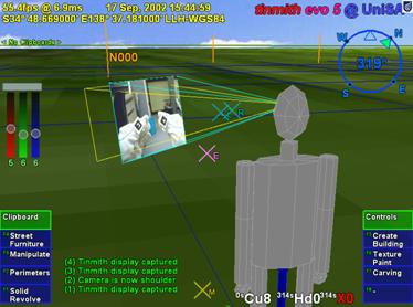
Figure 5‑12 External view of Tinmith-Metro with user’s body and 3D
environment
The
projection video is forced close to the user in this view
|
The user interface design is integrated
into an example modelling application I have developed, named Tinmith-Metro [PIEK01b] [PIEK03c]. This application implements AR
working planes, construction at a distance techniques, and the glove-based user
interface described in this dissertation. This section discusses some of the
implementation specific features that have been added to create a fully
functional application. This is provided to give an understanding of the number
of commands provided and the user’s experience while modelling. While this
example implementation is quite extensive, it does not define actual
limitations and so many other features can be implemented within the framework
discussed.
5.5.1 Top-level menu
|
Figure 5‑13 Options available from the top-level of Tinmith-Metro’s
command menu
|
Figure 5‑13 is an enlarged view of
the menu nodes displayed in Figure 5‑7, and shows the top-level options
that are available to the user. These commands represent tasks that are most
commonly performed by users of the application. Since there are more tasks than
fingers available, some less used tasks are nested in sub-menus. In this
example there is one spare menu slot remaining for future expansion and others
can be made available by rearranging the hierarchy. The clipboard and controls
menus are unique in that they perform overall system functions, and so are
mapped to the special palm gestures. The clipboard and controls menus are
configured so that when these sub-menus are entered, the same palm gesture is
used to return back to the top-level menu. In other menus the palm gestures are
used for ok and cancel operations - to quickly return to the top-level menu the
user may repeatedly press the cancel palm hand (depending on the nominated
dominant hand).
5.5.2 Task descriptions
The menu display in Figure 5‑13
represents the top level of the menu hierarchy depicted in Figure 5‑14.
Each menu node is broken down into a number of sub-tasks that are described in
this subsection. Labels were selected for the menus that would fit on the
display and be most familiar to the users, rather than using the actual full
technique names. The following description of the tasks contains names in
parenthesis that indicate the internal menu node from Figure 5‑14.
|
Figure 5‑14 Menu hierarchy of available options for the Tinmith-Metro
application
|
5.5.2.1 Controls (controls)
This menu contains controls for various
aspects of the system that affect its operation and does not perform any
modelling tasks. Various camera views (camera) such as 2D top down (above,
above_far, satellite), external body views (shoulder, shoulder_far, head,
orbit, orbit_far), as well as the standard AR immersive view (ok) may be
switched between. The current model may be saved to disk as a time stamped file
(save) without overwriting previous models. The menu orientation may be
switched between that of Figure 5‑13 (vertical) and Figure 5‑15
(horizontal), with vertical being the default. When testing with different
users, the system requires calibration to configure for the varying placement
of the position and orientation sensors. When the application first starts, the
IS-300 input must be initialised by the user placing the head cursor on the
horizon toward north and selecting the calibration option (orientation).
Another option is provided to offset the GPS if required (gps). Quitting the
running software is intentionally made difficult since it causes everything to
exit and is not performed very often. The option for quitting (quit) contains a
nested menu that requires alternating finger presses from each hand to prevent
accidental activation.
5.5.2.2 Street furniture
(create_street)
The creation of street furniture is
performed with this menu, and various prefabricated objects are mapped to options
so that they may be created at the user’s current location. The objects
available are those that occur commonly in the outside environment such as
boxes, humans, survey markers, trees, tables, rubbish bins, and lamps. With
larger collections of objects, hierarchies may be used to organise them more
efficiently. An unlimited undo option (undo) is provided to delete the last
object created. The ok gesture commits the active selection buffer to the scene
graph, while cancel deletes all the objects created.
5.5.2.3 Create building
(create_building)
This menu implements techniques suitable
for the modelling of houses and similar structures. Street furniture style
techniques (furniture) are provided for the placement of objects such as
humans, tables, boxes, windows, and water heaters. Orientation infinite planes
techniques from Chapter 4 are used for the capture of building structures
(create). When create mode is enabled, an infinite solid region is created
around the user that will be used as an input for future carving. The user then
walks around the physical world, and may create walls from the head cursor with
normals pointing to the left (left) or right (right), as in Figure 3‑9.
The specification of the direction of the walls affects the side of the solid
region carved away with CSG since planes have an inside and outside. For cases
where the user cannot align themselves along a wall, world-relative planes may
be created that face toward the user as in Figure 3‑10 at a fixed
distance (left_toward, right_toward) but these are not normally used. An
unlimited undo option (del_last) is provided to delete the last wall entered
and restore the solid region. The ok gesture commits the building to the scene
graph, while cancel deletes it.
5.5.2.4 Manipulate (manipulate)
This menu is used to perform all the
manipulation operations described previously. Free hand translation (move),
rotation (rotate), and scaling (scale) as well as fixed unit translation
(nudge), rotation (rotnudge), and scaling (scalenudge) are provided. The cursor
is used to select an object and any associated selection buffers. When the user
is satisfied with the new transformation, it is committed to the scene graph
with the ok gesture. The object can be returned to its previous placement with
the cancel gesture.
5.5.2.5 Texture paint (texture)
Polygons in the scene may have textures
applied to the surface, either prefabricated or captured using the head mounted
camera. Existing sample textures are provided for grass, bricks, and clouds.
Textures may also be cleared from a polygon and reset to the original base
colour (clear). The colour widget may be used to specify any solid colour input
by the user (colour). When camera mode is selected (video), the system selects
the polygon underneath the glove cursor and prepares it for texture mapping.
The final image is then captured from the camera and mapped to the surface with
the ok gesture, or aborted with the cancel gesture.
5.5.2.6 Perimeters (perimeter)
This menu implements the bread crumbs
technique, used to mark out perimeters along the ground. The user places down
markers (marker) and after three or more markers are placed down the system
connects them together in real-time into a polygon. At any time the polygon may
be set to one of three specified extrusion thicknesses from the ground plane: a
thin slivered polygon (set_flat), a 3 metre building (set_building), or an
infinite height object (set_infinite). The infinite height object is useful for
objects that are not slivers or 3 metres high and can be carved later on. The
direction the polygon is marked affects whether the polygon extrudes upwards or
downwards, with upwards being nominated to be clockwise (set_clockwise) or
anti-clockwise (set_anti_clockwise). The current position of the hands and the
colour widget may be used to nominate the surface colour (set_colour). An
unlimited undo option (delete) is provided to delete the last marker entered.
The ok gesture commits the final shape to the scene graph, while cancel deletes
it.
5.5.2.7 Carving (carving)
Existing objects in the system may be
modified using the cursor projection carving techniques described in Chapter 4.
The user projects markers against the surface of an object (marker), with the
first marker being used to nominate the object to carve, and create a
world-relative AR working plane at the surface. If one marker is placed, a
horizontal plane facing upwards is used to cut off the top of the object. Two
markers specify a plane at an angle to cut off the top of the object. Three or
more markers are connected into a polygon and extruded into the object,
removing all parts of the object that are outside this extrusion. As each
marker is placed the system shows in real-time the effect of the change so the
user may immediately verify its accuracy. The length of the extrusion is
normally infinite (infinite) but may be switched at any time to being a thin
sliver (thin) to carve slight surface features. The CSG carving operation
applied may be switched between the default (intersect) and difference which
inverts the extrusion and removes everything inside the selection instead
(difference). An unlimited undo option (delete) is provided to delete the last
marker and recalculate the carved object. The ok gesture commits the final
carved shape to the scene graph and deletes the original inputs. The cancel
gesture aborts the operation and restores the original inputs.
5.5.2.8 Solid revolve (revolve)
The surface of revolution technique from
Chapter 4 is implemented in this menu option. The user initially needs to
create an AR working plane and this may be projected with the head cursor
(data) as the most common case (as in Figure 3‑9), or placed pointing
toward the user (as in Figure 3‑10) at 1 metre away (one_plane) or 10
metres away (ten_plane). Once the plane is created, the user can project
markers against this plane (marker) using the cursor. At any time the user may
also specify the location of a vertical axis of rotation (axis) on the AR
working plane. With an axis of rotation specified the system will calculate the
surface of revolution and provide real-time updates as changes are made. The
current position of the hands and the colour widget may be used to nominate the
surface colour at any time (set_colour). An unlimited undo option (delete) is
provided to delete the last marker entered. The ok gesture commits the final
shape to the scene graph, while cancel deletes it.
5.5.2.9 Clipboard (clipboard)
Clipboards have been previously described
as selection buffers and provide collections of inputs to modelling tasks.
Working with these buffers is normally transparent to the user since most tasks
are performed with a single object and the system automatically sets up
temporary selection buffers. When the user desires to work with collections of
objects, this menu is used to gather multiple objects into selection buffers.
A new selection buffer is created and
made active when a user nominates an unselected object (obj_select). If an
object is nominated that is already part of another selection buffer it will be
transferred to the current buffer. The alternative is to select a buffer
(clip_select) by nominating an object, and the buffer containing this object
will be made active. If no buffer is active then one will be created and the
object added to it. New selection buffers may also be created and made active
without the selection of an object (clip_create).
The entire list of objects in a buffer
may be deselected (clip_clear) or deleted from the 3D world (clip_delete). As
previously discussed, selection buffers maintain a circular list with a pointer
indicating the last object that was added. The circular list may be rotated
(clip_rotate) to shift a different object to being last. The last object in the
active selection buffer may be deleted from the 3D world (obj_delete). Since
the system supports a hierarchy of models, the selected object may not be at
the desired level in the hierarchy. The last object added to the buffer may be
expanded (obj_expand) and the selection is adjusted to include the geometry at
the next level up in the hierarchy.
The user interface was developed using an
iterative design approach to take initial ideas and then produce a more mature
interface over time. At each stage of the design, the Tinmith-Metro modelling
application was used to test the interaction techniques with both myself as
well as novice users to gain their feedback. Brooks discusses insight into the
design of user interfaces and states that the uninformed and untested intuition
of the designer is almost always wrong [BROO88]. He suggests that interfaces must
be refined with real users, and this section discusses the studies performed
and the changes that were made based on this feedback.
5.6.1 Initial design
As discussed previously, I decided that
the use of tracked pinch gloves for pointing and command entry would be an
efficient way of interacting with 3D objects in an outdoor AR environment. The
initial idea was to use gloves with metallic pads that would allow finger tip
to thumb, finger middle to thumb, and finger tip to palm inputs (similar to the
Kitty hand worn keyboard [KITT02]), with a total of 24 menu options
(12 for each hand) available at any time to select from. While allowing a large
number of items at any particular time, I found this design to be uncomfortable
when I tried to select all 24 inputs. The presentation of 24 menu options on
the display would also produce a confusing menu for conveying the appropriate
finger mappings and consume a large amount of screen area. To keep the menu
simple and within the limits of human dexterity, the design was reduced to
having a single menu node for each finger, and by pressing the fingers into the
palm the menu would reset to the top level. To present the layout of the menu,
a horizontal strip of menu options was fixed across the bottom of the display
to correspond with the layout of the hands when they are laid out flat. Figure 5‑15
shows the layout of the user interface with the horizontal menu options
presented within a transparent green window.
5.6.2 May 2001 studies
The initial user interface implementation
was designed to support the first Tinmith-Metro modelling investigations [PIEK01b]. The first evaluation of the
design with a functional application was performed in May 2001. This evaluation
was performed by my supervisor and I, who were both very familiar with the
Tinmith-Metro software and user interface. The menu system worked quite well
for selecting commands, as the menu labelling was easy to read and the menu
item to finger mapping was straightforward. A problem discovered quickly during
trials was that the menu layout was too complex and designed to reflect every
single primitive operation provided by the modelling engine. This menu layout
was too generic in that every operation was customisable, and made most tasks
too difficult or time consuming to perform. Based on this observation, the
menus were later redesigned and simplified in April 2002 to be more task
oriented. Since the user will be performing common tasks most of the time these
need to be made as simple as possible.
|
Figure 5‑15 Original horizontal menu design in immersive AR view
|
5.6.3 August 2001 indoor VR
studies
The user interface was also tested with
an indoor VR application as shown in Figure 5‑16, where a similar
modelling application was interfaced to a Polhemus magnetic tracker [PIEK02e]. While the user interface works
well indoors, I have not performed a formal user study to compare it against
existing VR techniques. Since the totally immersive VR system blocks out the
view of the physical world, the user is not able to see their hands. The user
cannot take advantage of the visual mapping between the menu items and their
fingers, and they must rely on their own sense of proprioception instead. The
main intention of the VR work was to demonstrate that the new user interface
was useable across both indoor and outdoor applications. This allows people to
use one interface to control environments in a variety of locations without
relearning new interactions.
5.6.4 October 2001 studies
The first Tinmith-Metro application was
taken to five different institutions in Europe and the USA in October 2001 to demonstrate the user interface to various researchers and get their feedback.
Before using it themselves, the users (a total of 8 from the various
institutions) were given a brief presentation explaining how the fingers map to
the menus and then a live demonstration. After the initial distraction of
viewing the Tinmith-Metro application (in some cases using an AR system for the
first time) users were able to navigate through the menus and perform simple
object manipulation tasks. Initially, users were slightly confused by the
availability of up to 8 selection fingers instead of using only the pointer
fingers as most people are familiar with. A number of comments were made that
the horizontal menu strip was difficult to understand because when using the
interface the user must hold their thumbs up and hence the hands are held
vertically - having the menus in a vertical orientation would be more
appropriate. Comments were also made that pinching and cursor movement with the
same hand causes unexpected cursor motion. By using the non-dominant hand for
pinching and the dominant hand for cursor manipulation, these spurious hand
motions can be prevented.
|
Figure 5‑16 View of the user interface being tested in a VR immersive
environment
|
5.6.5 May 2002 studies
To support my new construction at a
distance techniques [PIEK03c], the user interface was modified
based on the comments from the previously described experiences. The menu
strips were modified to be vertical, and employed a more compact and efficient
layout (as used in the latest Tinmith-Metro). The menu hierarchy was redesigned
to be more task oriented and user friendly. Many of the features that were
thought to be important previously were either never used or not required for
the new simplified modelling techniques. The removal of these features allowed
for a greatly streamlined command structure. An example of a feature that was
removed is the menu options to allow the use of trackball mice and head cursors
to perform manipulations on objects. These manipulation options were never used
since the gloves could perform the same tasks easier, and so the gloves are now
permanently activated. Another new feature is the extra green boxes at the top
of the menu - rather than automatically jumping to the top-level menu during a
palm press, the menu shows the command for when this gesture is used on each
hand. A common use of the palm mapped gestures is for ok and cancel operations,
depending on which hand is nominated to be dominant by the user. As a result of
these changes, the interface was more user friendly and less reflective of the
implementation details. When I tested the new Tinmith-Metro outdoors, the
improvements in both the menu design and the construction at a distance
techniques allowed me to more easily model structures with greater complexity.
5.6.6 September 2002 augmented
reality class
During September 2002 I helped present a
two day course on AR technology at the University of Tampere in Finland. As part of the course, the students were able to take the Tinmith-Metro
application outdoors and use the street furniture application to experience AR
modelling first hand. As in previous studies, the students were given a
presentation about the user interface and then shown a live demo to see the
system operating. In this study approximately 30 students participated and only
5 of them had any prior use of a HMD, with none having any AR experience. The
overall trial ran for just over 3 hours and each student used the system for
approximately 5 minutes, including time to don the equipment. Since the users
had no previous experience with AR systems, initially they were surprised and
pleased with the augmented overlay of 3D objects. The users were talked through
the process of creating several prefabricated objects and then manipulating
them using the hands. While most users required a minute or two to become
familiar the interface and made several mistakes, some users were very fast in
adapting to the new interface.
Some users experienced difficulty with
manipulating objects. The move task required the use of both hands, one to
control the menu for start and stop commands and the other to perform the
manipulation. This was discussed previously and implemented to avoid having the
same hand perform both tasks. I observed the users attempting to use the same
hand to select an object, drag it, and then release the fingers to drop it. The
mental model employed by the users was similar to that used with a desktop
mouse dragging an object. Unfortunately the model must be more complex to
support many operations using only a small number of inputs. Another
observation was that many users did not seem to notice the menu boxes changing
colour to indicate they selected the item, and required more feedback to know
what was happening. Currently a beep is emitted at the end of each operation,
but the meaning of this beep is hard for novice users to understand what has
happened. The volume of the beep was also too low for a noisy outdoor
environment; it was quite windy during the trials outside and people were also
discussing the live AR view on the laptop display. The most difficult part of
this evaluation was that it was initially quite intimidating for the user since
they were being asked to perform many tasks straight after wearing an AR system
for the first time in their life.
5.6.7 Various 2003 trial results
During testing and demonstrations of
Tinmith-Metro, I have gained considerable experience with the application and
gained an insight into the user interface. An interesting side effect of the
suggestion by Brooks that commands and operations should be separated is that
hand/arm fatigue was not found to be a problem when using the system outdoors.
With most of the commands being performed not requiring an input cursor (except
hand-based manipulation, scaling, and rotation) the menu can be easily
navigated with the hands at rest on either side of the body. If head-based
pointing is used in preference to the hands, the time with the hands at rest
can be further increased. By providing a number of different cursors and
manipulation techniques, the user is also given a choice as to how they would
like to perform the required task. The best technique to use depends on the
user’s skills, the environmental conditions, and their personal preference. The
most sensitive form of interaction is the one and two-handed cursor techniques,
since they rely on adequate tracking of the hands which is more difficult than
tracking the body and head. The vision-based tracker in use suffers from
failures when lighting conditions are too bright or too dark, and is not able
to track the hands when the image is blurred due to fast motion. In this case,
the user is still able to translate, rotate, and scale the object using the
nudge commands, or translate the object using the head cursor. Since the head
tracker is very fast and smooth, the user is able to easily move around objects
attached to the head cursor. The question of whether hand or head movements of
objects outdoors is superior given the tracking conditions available is still
an open problem and would be interesting future work.
The start of this chapter described how
speech technology was not feasible for implementation in this user interface.
There have been a number of recent improvements in speech engines with
commercial products such as Nuance, IBM ViaVoice, Dragon Dictate, and Microsoft
SAPI. These systems are still very CPU intensive and are developed to work on
the latest processors, and so require a second computer to be realisable. The
second computer may be either attached to the backpack or placed indoors with
the speech audio and recognised text being transmitted using a wireless
network. I would like to implement speech controls for the menu so that the
user can either supplement the existing glove command entry or replace it with
speech entirely. Speech recognition allows extra commands to be added beyond
the ten currently available at any menu node and improve the flexibility of the
user interface. The accuracy of the speech engine may be further enhanced by
supplying a limited grammar of available commands generated from the menu
hierarchy.
With a stable user interface to use as a
benchmark, performing formal user studies comparing newly designed input
techniques is now possible. Interfaces such as speech could be trialled, as
well as comparing against 2D input devices such as trackball mice and tablets
to verify whether the direct 3D manipulation interface really is an
improvement.
This chapter has presented the design of
a new user interface I have developed for use with mobile outdoor AR systems.
This user interface is designed to be implemented within the limits of
currently available hardware so that it can be tested and iteratively refined.
Vision tracking and fiducial markers placed on the thumbs of gloves worn on
both hands are used to supply input cursors for selection and manipulation. A
screen-relative menu system is provided where up to ten possible commands are
mapped to pinches and palm gestures with the user’s fingers. Interaction modes
with zero, one, or two-handed input techniques are provided to manipulate
objects with translation, scaling, and rotation operations based on AR working
planes. The user interface is also used to control construction at a distance
operations and create markers against the underlying AR working planes. The
interface also uses a number of display-based techniques that are needed to
provide user feedback and develop useable modelling applications. Various
features such as 2D and 3D overlays are useful for presenting necessary
information, and external VR views of the body are used to gain situational
awareness not normally possible from within an AR immersive view. By informally
evaluating the interface, insight has been gained from untrained users as to
how intuitive the interface is. This feedback has been used to improve the
speed and efficiency of the user interface. The Tinmith-Metro application was
developed using this interface to demonstrate its usefulness for supporting
complex AR modelling applications.
6
“A fax machine is just a waffle iron
with a phone attached”
Abraham Simpson
This chapter presents a new software
architecture that I have developed, named Tinmith-evo5, for the development of
the applications described in this dissertation. In order to implement a
modelling application with AR working planes, construction at a distance, and
user interface, a complex underlying infrastructure is required to simplify the
development. Currently there are a limited number of existing toolkits for the
development of 3D virtual environment applications, but each is optimised for a
particular feature set different from the ones that I require. Tinmith-evo5 is
designed for the development of mobile AR and other interactive 3D applications
on portable platforms with limited resources. The architecture is implemented
in C++ with an object-oriented data flow design, an object store based on the
Unix file system model, and also uses other ideas from existing previous work.
The Tinmith-evo5 software architecture addresses the following problems
currently affecting mobile AR and similar environments:
· Hardware changes rapidly over time, and so should be abstracted to
allow portability across different environments without changing the source
code.
Mobile AR is limited by portability constraints
and choices must be made between large and powerful or small and less capable
equipment. Software for outdoor use must be efficiently designed and be able to
run on mobile hardware that may be a number of generations behind current state
of the art indoor computers.
3D
graphics systems traditionally operate using a flat Earth model and do not
readily deal with large areas of the planet that can be roamed with a mobile AR
system. Being able to handle coordinates that span a wide range of scales, from
millimetre-level tracking of the hands to moving over hundreds of kilometres of
land is required.
User
interfaces for mobile AR are quite primitive and there is limited toolkit
support for developing applications. This problem is difficult to solve and
current development in this area is quite immature.
This chapter begins with a design
overview, followed by a summary of previous work describing existing systems
and their features. The design of the architecture is then described, including
concepts such as data flow and object distribution. The object storage system
forms a core part of the architecture and is described in the following
section. The next section describes the more interesting aspects of the implementation
of the software. The abstraction of trackers and sensors with four different
representations is then described. The usefulness of this software architecture
is demonstrated with the applications developed for this dissertation and a
number of extra demonstrations presented at the end of this chapter.
Three dimensional environments are a
challenging area to develop applications for since hardware devices are
constantly evolving and non-standardised, there are a number of approaches to user
interface design, and each application has different requirements. In 2D
desktop environments, similar problems are better understood and high-level
software toolkits are available so developers can focus on writing applications
rather than implementation details. With 3D environments being newer and less
understood, most available software toolkits are simple and low level, such as
hardware abstraction layers. Shaw et al. explain how the development of
high-level software is not possible until there is a stable base of low-level
toolkits to support them [SHAW93]. Beyond simple abstractions
however, there are only a few software systems that attempt to address
higher-level problems and each is designed for supporting particular types of
applications. This chapter develops a high-level architecture that is
demonstrated with a mobile AR modelling application but may be also useful in
other application domains.
The first main concept used in the
software architecture is that of data flow. Figure 6‑1 depicts this data
flow from an overall perspective, with sensor data arriving into the AR system,
being processed by specific application code and configurations, and then
rendered to the HMD of the user. The data flow model is supported by the use of
objects to perform specific actions such as processing tracker data, combining
results, and rendering 3D graphics. Objects allow problems to be broken down
into simple tasks to simplify software development. Objects are connected
together into a directed graph, and as new values enter the system, the values
are processed through the graph as a flow of data, adjusting the current state
and eventually rendering to the HMD. These objects can be distributed across
multiple processes or computers in units named execution containers, with the
data flow occurring over a network when required.
|
Figure 6‑1 Overall architecture showing sensors being processed using
libraries and application components, and then rendered to the user’s HMD
|
Research toolkits are designed using many
different methodologies and are difficult to use together because of
conflicting requirements. In the future these may become standardised but for
now I avoid trying to make immature and opposing toolkits work directly
together so that I can perform research into new ways of developing software.
All the components of the architecture are developed from the ground up using a
common methodology, with abstractions to hide away any differences from
external libraries that are required. The goal is to not to treat the
application as a combination of scene graph, tracking library, and shared memory,
but instead as a single entity with blurred boundaries.
As part of the integrated component
design methodology, the entire system has been structured around the model of a
memory-based file system. Instead of using global variables to reference the many
objects available in the system, an object storage system based on Unix file
system semantics provides a logical interface that is easy to understand. All
objects that process data in the system are stored in this object repository,
making them accessible to other objects in the system through discovery at run
time. The ability to perform distribution across multiple computers is added as
an extra component using object data flow, and is not an internal part of the
architecture that imposes a constant performance penalty whether in use or not.
The most important goal with the design
of this software architecture is performance. Due to limitations in wearable
computer hardware, it is important that as much work as possible be extracted
out of the resources available. The C++ language and optimising compilers are
used for all development, supporting both low-level code and high-level
features such as object-oriented programming. The renderer that forms a core
component of most applications is implemented using OpenGL and provides high
performance graphics support when 3D acceleration hardware is present in the
system. The software has been used on a number of small and relatively slow
computers and is capable of running adequately in most cases, the exception
being the rendering of large 3D scenes.
There has been a wide range of previous
work in the area of software toolkits for the implementation of VE
applications, although there is no complete solution and is still an active
research area. Shaw et al. describe how developing high-level tools requires a
good understanding of the types of interactions, as well as low-level toolkits
to provide necessary support. To support this statement, Shaw et al. explain
how high-level tools for 2D user interfaces did not appear until researchers
gained sufficient experience developing interfaces with this style. These
high-level tools also did not exist until other more low-level toolkits were
created to provide the necessary services. Currently the VE area is still quite
immature when compared to 2D environments, and so more understanding is
required to implement a usable toolkit.
This section discusses a number of low
and high-level toolkits that have been developed to help implement VE
applications efficiently. There are a number of areas that need to be
addressed, such as data distribution, rendering, user interaction, tracker
abstractions, and rapid prototyping. There is no single toolkit that solves all
problems however, as tradeoffs must be made to support one feature at the
expense of another. Tinmith-evo5 uses many of the ideas developed in these
toolkits and applies them to the problems that need to be solved for mobile
outdoor AR. Software architectures for areas such as wearable context awareness
or other high-level information sharing are not described since they do not
support 3D user interfaces.
6.2.1 Hardware abstraction
libraries
Virtual environments typically require
the use of tracking devices that measure three or more degrees of freedom.
Tracker abstraction layers are implemented to hide away various differences in
hardware and provide a common model so that the application only needs to be
written once for many devices. Similar abstractions are commonly used for 2D
desktop input devices such as mice and keyboards. Researchers such as Shaw et
al. and Taylor et al. identified the need to have these abstractions in 3D
environments and implemented software toolkits such as the MR Toolkit [SHAW93] and VRPN [TAYL01]. Shaw et al. saw the MR Toolkit as
being an important low-level component for future development of higher-level
user interface libraries. With many VE systems of the time being implemented
using multiple computers, both MR Toolkit and VRPN are designed to support the
transmission of tracker updates via packets on a network. Trackers can be moved
to different machines or replaced with different devices without requiring any
changes to the source code of the applications that use them.
Other toolkits have also been developed,
increasing the levels of abstraction beyond just input devices: Hubbold et al.
developed the MAVERICK system [HUBB99], Bierbaum et al. developed the
VrJuggler libraries [BIER01] [BIER98], and Kelso et al. developed the
DIVERSE libraries [KELS02]. Each of these systems provides an
inner kernel that connects together various components such as input
abstractions for trackers, support code for processing data, and output
abstractions to various rendering systems such as OpenGL, IRIS Performer, and
Open Inventor. These systems all provide similar functionality to those
discussed previously, providing network transport for tracker device updates
and the ability to modify configurations either at startup or at run time
without modifying source code.
Another recent tracker abstraction is
OpenTracker by Reitmayr and Schmalstieg [REIT01b]. It implements abstractions
similar to those discussed previously, but in the form of a filter graph for
arbitrary processing. Three different types of object nodes are provided:
source nodes to read values from trackers, filter nodes to take source values
and perform operations such as smoothing and conversions, and sink nodes to
take the results and output them to other parts of the system. Using XML
configuration files, the user can define complex filter graphs without
requiring source code to be modified.
Other more high-level libraries (such as
Coterie [MACI96], Division’s dVS [GRIM93], and the Sense8 World Toolkit [SENS03]) discussed later in this section
also include abstractions similar to those previously mentioned.
6.2.2 Distributed entity systems
One current area of investigation is the
implementation of distributed virtual environments. This involves simulating
entities on machines and then viewing them on remote clients over a network.
The main focus of this research is on the protocols rather than the toolkits,
such as SIMNET by Calvin et al. [CALV93] and NPSNET by Zyda et al. [ZYDA92] that use protocols similar to DIS [IEEE93]. These protocols are not able to
send full scene graphs or object databases, but instead only send position,
orientation, and other simple data for each entity. The client viewer is
responsible for supplying the models and performing the rendering, which is not
defined by the protocol. By making these restrictions however, these systems
are efficient and tend to scale up to large numbers of entities and computers.
Other systems such as the previously
described BARS extend the distribution of data to wearable computers. Brown et
al. describes the development of a data distribution mechanism for events to
support collaboration between multiple users [BROW03]. Since the system only propagates
events, complicated geometry and animation are not transmitted over the network
and are assumed to be stored locally. The propagation of events may be used to
convey objectives to mobile AR wearable users, communicate messages and
reports, and update entity locations and attributes in a database.
A common problem with many distributed
systems is that network data is decoded using fixed programs that can only
handle protocols known in advance. For example, software that handles DIS
protocol requires modifications if any of the enumerated values change meaning.
These problems are addressed by Watsen and Zyda with the Bamboo system [WATS98a] [WATS98b]. Instead of having a single
monolithic code base, Bamboo contains a small kernel that can perform the
loading of other modules. When information arrives from the network that cannot
be decoded, a request is sent for a decoder object. When the decoder object
arrives, Bamboo loads it into memory so that the incoming packets can be
processed. Bamboo uses a plug-in architecture to allow reconfiguring of
software at run-time, and does not require modules to be stored locally. Other
systems such as Octopus by Hartling et al. [HART01] also support distributed VE
applications based on similar protocols to that used in Bamboo.
6.2.3 Software systems
There are a number of software systems
that implement higher-level abstractions, using concepts previously described
as a base for further development. Two early commercial toolkits are dVS by
Grimsdale [GRIM93] and the World Toolkit by Sense8
Incorporated [SENS03]. These are both designed to be used
by developers to develop interactive VE applications involving many computers,
different tracking devices, and various kinds of output technology such as
video and audio. dVS is implemented using an architecture based on the concept
of actors. Each actor performs a task such as display or sensor inputs, and
these run in parallel and communicate with each other. This parallelism
naturally supports multiple users for collaborative tasks. World Toolkit also
provides a wide range of features such as a scene graph, abstractions for absolute
and relative tracking devices, objects containing properties, the ability for
properties to trigger events, and sharing of data across multiple machines.
There are a number of rendering and scene
graph libraries available, with the most commonly used ones being based on
hardware accelerated OpenGL calls. OpenGL was first developed by Silicon
Graphics and provides low-level interfaces to produce realistic 3D graphics
while hiding this complexity from the application programmer. To provide more
functionality for application development, Silicon Graphics developed Open
Inventor [STRA92] and IRIS Performer [ROHL94]. These are both scene graph
libraries but Performer is designed for high performance visual simulation
applications while Inventor is used for more complex user interfaces. Similar
capabilities for rendering scene graphs are provided in Sun Microsystems’
Java3D libraries [SUNM97].
Scene graph libraries require a format to
represent objects when they are being stored or transported across a network.
The VRML 2.0 standard was developed by the VRML Consortium [VRML97] and is a declarative language
specifying the layout of a scene graph, with a format similar to that developed
for Open Inventor. VRML also includes numerous features for implementing interactive
applications [CARE97], such as fields and routes. Objects
in VRML contain attributes referred to as fields, with inputs such as the
centre point, radius, and other values that control appearance. Object
attributes may also be used to provide output events, such as when a virtual
switch is flicked the field will generate a Boolean event. By using a route
command, input and output fields may be connected so that one object can cause
changes in another. Using fields and routes implements a kind of data flow
approach where changes propagate from one object to another by linking them
together.
The research system VB2 by Gobbetti and
Balaguer [GOBB93] is designed to demonstrate the use
of constraints to implement relationships between objects in virtual
environments. When an object has been grabbed and a tracker generates an
update, the constraint engine propagates these values into the scene graph,
allowing the user to alter the position and orientation of objects. Constraints
are one possible method of implementing the flow of data between various
objects in a system.
The ALICE system [PAUS95] is a high-level authoring tool
allowing novice users to implement VE applications. The user can specify object
behaviours using a scripting language and then interact with the environment,
exploring various possibilities. Since ALICE is more of an authoring tool, it
is not designed to be extended beyond the features accessible with its
scripting language and provided function calls.
The Lightning system by Blach et al. [BLAC98] is based on scene graph and data
flow concepts developed by Inventor and VRML. A pool of objects is created and
maintained by the application, and these are connected together to take events
from various objects, process them, and then render them to the display.
The DWARF system by Bauer et al. [BAUE01] is designed as a framework for the
development of augmented reality applications. A complete system is built up
using a number of components which provide services that are made available
using CORBA. The DWARF framework is used to connect these services together
within a local host or over a network.
6.2.4 Fully distributed systems
Many of the previously described systems
only distribute small parts of their internal state to provide data for other
applications. The following systems provide more complete distribution, where
entire applications and scene graphs are synchronised between multiple hosts to
make complex collaborative applications possible.
The Coterie system was developed by
MacIntyre and Feiner to help implement applications for distributed virtual
environments [MACI96]. One example of Coterie in use was
for the development of the Touring Machine by Feiner et al. [FEIN97]. MacIntyre and Feiner identified a
number of problems with simple tracker abstractions and set to develop a more
complete solution. Coterie is implemented in Modula-3 and uses modification of
language-level primitives to support the implementation of a distributed shared
memory. This is integrated with packages that support an in-built interpreted
language, threaded processing, tracker abstractions, and 3D animated rendering.
Multiple threads in the system execute code within objects and communicate via
a distributed shared memory, with each update method call passing through a
sequencer to ensure accurate synchronisation between processes. All the
components of the system are developed to use this shared memory, including the
distributed scene graph Repo-3D [MACI98].
Frecon and Stenius developed the DIVE
system [FREC98] which is based on previous distributed
entity research. Instead of just generating entity updates, this system is
capable of propagating nodes in a scene graph without requiring previously
stored descriptions in the remote host. Nodes introduced into the scene graph
are not controlled by any particular software instance, and so once created the
software instance can disconnect and the scene graph nodes will remain in the
memory of other running instances. Updates are handled by sending compact
differences against previous objects using a multicast protocol, reducing the
bandwidth used for the transmission of updates.
The current Studierstube framework
described by Schmalstieg et al. is used for the implementation of various
distributed AR applications [SCHM00]. Studierstube also interfaces to
the previously described OpenTracker libraries [REIT01b]. The original Studierstube
framework was based on Inventor and is used to implement new user interfaces
such as the Personal Interaction Panel [SZAL97]. The Inventor toolkit was then
extended by Hesina et al. to produce a distributed version that propagates
changes in the scene graph over a network [HESI99]. Applications must use
Inventor-based objects for all rendering and user interface components, and so
certain operations like drawing 2D overlays on a 3D scene are difficult because
Inventor does not support these. Since Studierstube is limited to distributing
values that are contained within the scene graph (under the control of
Inventor), any other application data will not be synchronised between instances.
Schmalstieg and Hesina describe how internal application values can be stored
within objects extended from Inventor base classes [SCHM02]. These application values then can
be stored in the scene graph and distributed like any other graphical object.
While MacIntyre and Feiner’s system implements all applications using shared
memory, the work by Schmalstieg et al. performs the opposite and implements
everything inside the distributed scene graph. By embedding entire applications
into the scene graph Schmalstieg and Hesina demonstrate how applications can be
migrated between separate computers through the distributed scene graph, and
processing of inputs can be distributed easily across multiple instances.
The Avocado framework by Tramberend [TRAM99] is similar in design to both
Distributed Inventor [HESI99] and Repo3D [MACI98] for distributed scene graphs over a
network. Avocado is based on Performer and so is designed primarily for use in
complex visualisation applications. Tramberend extended the base Performer
objects with a wrapper that provides storage of fields and the ability to
serialise them. Private inheritance and access methods are used to force
applications to work through this interface and updates are sent to the network
whenever changes are made. Fields can be connected together with field
connections, (similar to VRML fields and routes) and used to implement data
flow style connections between objects in the system. Sensor objects provide
Avocado with interfaces to tracker abstractions and service objects are used to
access low-level APIs. The Scheme scripting language is embedded into the
system so that parts of applications developed can be modified at run time
without recompilation.
This section describes the overall design
of the classes in the software architecture. Class definitions used in the
software architecture can be divided into four categories – those for
representing data values (data), those for processing input data values and
then producing some kind of output values (processing), those for implementing
core features that other classes can inherit or use (core), and helper code
that implements interfaces to streamline development (helper). Each class can
also be classified into one of the categories depicted in Figure 6‑2.
Applications require classes from both high and low levels to be instantiated
as objects and connected together. Each class can contain nested sub-objects of
other class types or primitive C++ values such as pointers, floats, integers,
and strings.
|
Figure 6‑2 Layers of libraries forming
categories of objects available to process data
|
6.3.1 Data flow
|
Figure 6‑3 Data values flow into a node for processing, producing
output values
|
Data objects in the system are used to
supply input for processing objects, which then produce an output data object
that can then be propagated to other processing objects for further operations.
Figure 6‑3 depicts how this input data arrives at a node and is then
processed to produce new output. Objects can be connected together into a
directed graph that forms a flow of data through the system. Figure 6‑4
depicts how data values initially arrive as tracker inputs, and are then
processed in various stages of a virtual pipeline before reaching the user in
the form of rendered output. This figure depicts categories for the objects
used in various stages of the pipeline, but is only an approximate model.
The data flow model is implemented by having
processing objects listen to events that are generated by data objects. When
the data object changes to a new value, interested listening objects are
notified of this change via callbacks. This is similar to the
observer/observable pattern described by Gamma et al. [GAMM95]. Any number of processing objects
can listen in on a data value, and processing objects can have any number of
output values for others to listen to. The use of data flow to propagate values
through various processing objects has been performed in systems such as
OpenTracker [REIT01b] and Avocado [TRAM99]. The VRML concept of fields and
routes allows embedded scripts to process values when they change [CARE97] [VRML97]. Based on this previous work the
data flow approach seems an ideal solution, especially considering that 3D
applications tend to perform data processing in sequential steps.
|
Figure 6‑4 Expanded view of data flow model showing stages of
processing
|
6.3.2 Serialisation and
distribution
Objects in the system are represented
using the C++ compiler’s native internal format. It is not possible to simply
take the binary data for the object and directly save it to disk or transport
it across a network since it is specific to the running process only. The
ability to save the state of a running system and then restart it at a later
time or transfer it to another machine is desirable, and so a generic format that
can represent application state is required. Serialisation is not available in
C++ by default and so extra logic is provided to handle this requirement (the
implementation details are discussed later). A structured XML format is used by
default, with a binary format used to reduce the size of the data when
required. Nested objects are processed by recursively calling the serialisation
code and the results are assembled together for the top-level object.
The first use for a serialisation
capability is to store persistent configurations on disk. The XML header is
parsed to determine the object type, matching C++ objects are instantiated, and
are configured to contain the values in the XML data. When the application is
shut down these objects may be serialised back to disk so that it can resume
its previous state at a later time. The serialised XML files may be used as a
configuration system, and can be edited with a text editor or stored in a
database. These objects can also be modified and reparsed at run time to adjust
the application while in operation. This allows changing aspects of the
application without having to resort to slower interpreted language support.
While internal components such as network and disk interfaces cannot be
serialised in this fashion, the parts of the application that a user would like
to change are supported. Similarly, OpenTracker uses XML-based configurations
for filter graphs [REIT01b], VR Juggler uses text files for
tracker reconfiguration [JUST01], and Diverse uses compiled C++
modules switchable at run time [KELS02].
This serialisation capability may also be
used to implement distributed applications. An important feature is that the
system does not force the user to use this capability. In most cases,
applications are implemented as single processes and interactions between
objects occur using simple function call-based callbacks. The overhead of
supporting the callback updates is very minimal when only local data is used.
In contrast, many other systems require the application to use IPC interfaces
even when operations are being performed locally, taking its toll as a large
penalty on performance. Rather than use an internal architecture based around
distributed shared memory [MACI96] or a scene graph [HESI99] [SCHM02], the distribution of information
across multiple processes can be performed using objects in the data flow
model.
Figure 6‑5 part (1) depicts two
objects that are connected via callbacks, and the listener is notified when the
source signals a change has been made. Figure 6‑5 part (2) depicts how
objects can be inserted to implement distribution. When the source generates a
new value, the Tx object serialises the new value and then transmits it over a
network or other IPC mechanism. The Rx object at the destination receives the
incoming data, deserialises it in place using the same class and then signals
to the listeners of the object that new data is available. The listener object
then receives a callback in the same way as in Figure 6‑5 part (1). This
distribution mechanism is transparent to the listening objects since it is
implemented using the same interfaces as any other processing object. The
object store described later automatically provides network distribution when
required so that the programmer does not need to implement this functionality.
The mechanism used for distribution (via
callbacks and a possible network interface) is efficient because updates are
only sent to those processing objects that are interested. Each object is
stored on a particular server and other clients can make requests to receive
updates when changes are made. For small systems, this is more efficient than
broadcast protocols, although for large systems with thousands of processes
each requiring a value this may not be appropriate. By using proxy processes,
cached copies of values may be further distributed to others, which can assist
with scaling. If a client needs to change the master value, the server must be
configured to circularly listen for events from the client, or allow updates to
be forced in via the network command interface (described later in this chapter).
Any changes forced in by the client will be lost by the server when the next
incoming value arrives from the source, so this method is only practical when
the value is no longer updating.
|
Figure 6‑5 Network distribution is implemented transparently using
automatically generated serialisation callbacks and a
network transmission interface
|
Systems containing many objects that
interoperate require techniques to organise this complexity. This section
introduces the concept of an object store based on a model of the Unix file
system. This concept takes advantage of the ease with which users normally deal
with files on a disk, and how the storage of objects can be directly mapped
against the model and the benefits this provides.
6.4.1 Unix file system design
The Unix operating system (and clones)
implements a hierarchical file system to organise and store data [MCKU96]. File systems provide an
abstraction to simplify the storage of data on a disk that is otherwise just a
raw linear collection of fixed size blocks (typically 512 bytes). Files can
easily exceed the block size and so higher-level abstractions are required for
storage. An inode contains information about a file on a disk as well as a list
of ordered pointers to blocks containing data. Each inode contains a unique
identifier and is stored in a list at a fixed location on the disk.
Directory structures were developed to
store mappings between human readable text names and numeric inode values.
Directories are also stored using inodes and have an associated unique
identifier. Since both directories and files are represented using inodes,
directories can provide text names for other directory inodes and so form a
hierarchical tree structure. A top-level root inode (with identifier 0) is used
to represent the root directory (/) of the structure. Nodes in the tree can be
accessed by specifying the name of each directory joined together using forward
slash (/) characters. Path names that begin with a / character are referred to
as absolute paths and are relative to the top-level root node. Other path names
starting with a name are referred to as relative paths and are accessed from
the current working directory. Paths may contain aliases that have special
meaning - the name . (single dot) is a relative reference to the current
directory, while .. (two dots) is a relative reference to the parent of the
current directory. Each file and directory is named relative to its parent and
the full absolute path name is not stored anywhere. This allows changes at the
top level to be instantly inherited by all children.
Unix file systems implement hard links,
multiple directory entries referencing a single inode value. This allows the
same file to appear to exist in multiple locations but in fact is using a
single set of blocks on disk. Modifications to one file will immediately affect
others. Inodes store reference counts so that the disk blocks are not removed
until there are no more references. A second link type named a symbolic link is
used to provide a path name-based link to another file. Directory entries can
store mappings between names and inodes, and also names and other path names.
When the kernel encounters a symbolic link it performs a look up of the link
name to find the appropriate inode and then resumes the previous look up in
progress. Since symbolic links point to paths and not inodes, a destination
file can be replaced and all links to it will update automatically. Hard links
require each link to be changed since the inode number of the new file is
different.
6.4.2 Object file systems
One problem with systems that store large
collections of objects is accessing and updating them; the traditional approach
being the use of global variables. Each module that needs to reference other
objects must include definitions for the global variables, and suitable names
must be used to avoid namespace collisions. Having global objects requires the
compiler to statically declare these in advance, and hence cannot be changed at
run time to suit conditions. To overcome this problem, systems such as dVS [GRIM91] and COTERIE [MACI96] implement the concept of a
repository where objects can be stored for later retrieval based on a key. The
Windows operating system also implements a registry, which is a hierarchical
database of values stored on disk and used to configure the operation of the
system from a central location. These runtime style storage systems can be
modified without recompilation to store a variety of values, and do not require
statically declared objects. Programmers may independently write modules and
are only required to agree on the naming convention to reference the shared
objects. Referencing items stored within object-oriented databases has also
been implemented previously using query languages such as XML’s XPath [CONN02]. XPath allows for the searching of
objects meeting some kind of criteria (similar to SQL and relational
databases), but was not intended to be used for exact references like the Unix
file system model.
Tinmith-evo5 integrates a number of
concepts to develop a hierarchical object store. Instantiated objects in the
system are created in memory (statically by the compiler, or dynamically at run
time) and then a pointer reference is placed into the object store. Rather than
just implementing a hash of names to retrieve object pointers, the object store
is based around the Unix file system model described earlier. Path names are
used to traverse a tree of directories and files, and the inode values no
longer point to lists of blocks but are instead pointers to memory addresses.
These memory addresses are the locations of objects and method calls can then
be made just like with any C++ object. Figure 6‑6 depicts code fragments
that demonstrate the storage of objects, retrieval and modification, and
debugging.
|
Figure 6‑6 Examples demonstrating usage of the hierarchical object
store
|
On the surface, this file system approach
appears to give similar results to those achieved with other systems using
names to look up objects. The real advantages are gained when the Unix file
system model is taken to its full extent to provide a number of interesting
features. Hard links may be implemented by having multiple locations in the
hierarchy point to the same object address. This allows code to use new naming
conventions while still supporting older names for legacy source code. Symbolic
links can be implemented by storing a path name redirection, so when the object
store is traversing the internal structures it will recursively look up the
linked path names. Symbolic links implement much of the same functionality of
hard links, but may also be used to provide dynamic switching of objects. For
example, if a system contains both GPS (at /human/body/gps) and vision tracking
(at /human/body/camera), then a symbolic link can be created at
/human/body/tracking that points to the currently active tracker. The true
source of input devices may be concealed from the developer using symbolic
links as an abstraction layer.
During the implementation, I added
several optimisations to reduce memory consumption and unnecessary look ups,
and this resulted in the final version diverging slightly from the Unix file
system model. Instead of hard and symbolic links, I implement copy links and
pointer links, which have similar operations for some purposes, but some
notable differences. Copy links are similar to hard links but do not actually
share the same object pointer. Instead, a copy of the object is made for the
link destination, and whenever the source is changed the object store copies
the new updates into the destination object using data flow. The reverse is not
true however, and if the destination is modified it is not copied back. These
links were implemented using a copy since the object itself actually contains
its own name and parent pointer. This prevents multiple names sharing the same
object pointer but makes it possible for an object to quickly find its parent
without having to traverse from the root node. Pointer links are the same as
Unix-based symbolic links in that they store a path name redirection in the
object store.
6.4.3 Object hierarchies
In object-oriented languages like C++,
objects may be contained inside other objects, and this is referred to as
composition. Figure 6‑7 depicts how a simple object could be designed
that can store a position value for a location on the Earth. In this example I
use spherical (LLH) and grid-based (UTM) coordinates, with an object
implemented to represent each type. These objects would also normally have
methods to access the internal values and set them to desired values (not shown
in this example). Since coordinates in both spherical and grid-based formats
are commonly used, a Position object acts as a container for both types and
keeps the values synchronised using internal data flow processing. To gain
access to the internal LLH and UTM values, external code may reference these
directly if declared public or otherwise use access methods if declared
private.
|
Figure 6‑7 Simplified layout of composite Position class, showing
nested objects
|
Using the object store described
previously and the example in Figure 6‑6, the Position object could be
stored at the path /human/body/position. To retrieve an object pointer to this
object the call Position::getStorage(“/human/body/position”) is used. Using
standard C++, pointer->getLLH() or pointer->llh can be used to access the
spherical LLH values. When using a file system-based object store, it is also
logical to store references to the child objects at sub paths to the parent.
The spherical LLH child object can therefore be accessed directly using the
call CoordLLH::getStorage(“/human/body/position/llh”). Both the parent and
child objects are referenced in separate parts of the file system tree, but
still remain joined together as a single object and so are still accessible to
traditionally written code. The other advantage to this scheme is that since
the file system is dynamic and can be traversed, child objects may be added or
removed at run time (not just at compilation), and accessed without statically
compiled names. Code can discover and access the contents of objects easily,
allowing the writing of very generic code. Given a Position object, the call
pointer->getNode(“llh”) can be used to dynamically retrieve the LLH child
object from the parent. While objects added at run time are not visible to
standard C++ code, dynamic access, serialisation, and callbacks are fully
supported.
Many OO-based languages implement
containers to store objects based on a key: C++ implements STL hashmap, Java
implements HashMap, and SmallTalk implements Dictionaries. Some systems have
been implemented that use containers to implement hierarchical structures of
stored objects. An alternate implementation is to use the entire path as a
single key, but this is not hierarchical storage. All of these implementations
are different from my object store because they only store pointers to an
object but do not handle the child objects contained within. Languages such as
Java and SmallTalk support the run time discovery of child objects but the use
of a consistent file system approach for all levels of the hierarchy is not
performed. The file system approach is even more useful in languages such as
C++, where run time discovery is not normally available.
The Tinmith-evo5 architecture is
implemented in C++ to allow for an efficient implementation of the software.
There is very limited run time support (avoiding features such as garbage
collection) to hinder performance and compilers can generate optimised code,
making it ideal for machines with limited resources. The C++ language does not
provide some of the features needed for the implementation of the desired
software architecture, so extra code is supplied to provide these. This section
describes some important implementation details for the software architecture.
6.5.1 Class definition and code
generation
C++ is a statically compiled language
that provides object-oriented programming with inheritance, support for
templates, and a macro pre-processor. Each object that is a part of the
software architecture is required to inherit the abstract class Storable to
provide interfaces that the object store and serialisation components require.
A custom developed code generator TCC is used to generate internal information
for each object. The Storable class uses this generated information to provide
the discovery of internal objects, with the standard C++ RTTI functionality
being too limited to use. A sample C++ object for an InterSense IS-300 tracker
is demonstrated in Figure 6‑8, with object and method declarations
depicted. Special wrapper macros are used to indicate callback functions and
internal variables that should be processed. These macros pass through during
C++ compilation but are used by TCC to easily find the desired values without
having to write a full C++ parser. The code generation is performed
automatically because it is tedious and error prone for humans to do this by
hand. When internal changes are made, TCC is used to regenerate the derived
code in a separate file which is hidden from the programmer. Separate
definition files (such as used by CORBA and SUN RPC) are not transparent and
require the programmer to keep the definitions synchronised with the
implemented source code.
|
Figure 6‑8 Edited extract from the is-300.h orientation tracker C++
definition file
|
Figure 6‑8 depicts statically
compiled methods such as getOrientation() and getMatrix() that are used to
access internal values in the object. Inheriting the Orientationable and
Matrixable interfaces in the class implements polymorphism and the use of the
class as a generic tracker. The internal Storable methods getVarList(),
getVarType(), and getVarPointer() are used for the run time discovery of object
contents, providing similar functionality to SmallTalk and Java. The
getNode(“name”) method is implemented by Storable and can be used to traverse
to children objects, and is also used by the object store. The use of these
method calls does add small overheads for look up against internal object
tables, but only has to be used when static references are not possible.
This object discovery mechanism is used
to automatically implement serialisation functions. Storable implements toXml()
and fromXml() methods that can write out objects in an XML format that is human
and machine readable. An alternate format is with the toBinary() and
fromBinary() methods that use a compact binary representation in an endian
neutral format. An important limitation of serialisation is that it cannot
handle process specific values such as file descriptors or graphical handles,
and so these must be implemented using manually written code. To give an
indication of how data is serialised into XML format, an example is depicted in
Figure 6‑9. While this figure is very verbose and human readable, the
data can be compressed considerably by removing white spaces and using
shortened representations of the reserved words.
6.5.2 Callback propagation
|
Figure 6‑9 Complete XML serialisation of the IS-300 orientation
tracker object
|
The data flow model described previously
is implemented using pointer-based method callbacks. Instead of statically
defining specific methods to be called when an event occurs, a pointer to any
method defined with GEN_CALLBACK_H may be used. A single callback may listen to
a number of event sources and a pointer to the modified object is passed as an
argument to delimit between many objects. These callbacks are simple and
efficient to perform since they involve a pointer dereference and then a
function call, which is only slightly more overhead than using static function
calls.
When a callback is attached to an object,
it will be notified whenever the object or any of its children are changed.
When an object is modified it will execute the handlers attached at that level
of the object store, and then work up the hierarchy of the object store
executing handlers until it finds an object that is not contained within a
parent object. The execution of callbacks is automatically implemented for copy
and set operations using C++ operator overloading, so the programmer does not
need to be aware of this mechanism. For objects containing internal C++ values,
these must be stored privately and wrapper methods written that generate
callbacks. Figure 6‑10 is a code fragment depicting how callbacks can be
configured and then executed. The first set of code retrieves an object pointer
from the object store and then uses the setHandler method to specify the
callback method. The second set of code uses access methods to modify the
internal values individually. The disadvantage to updating in this way is that
callbacks are propagated for each modification and there is no way to indicate
to the system that changes may be performed as a single unit (the programmer
never calls an update method). The faster and preferred method depicted in the
third set of code is to declare a new temporary object and initialise the
values to those desired. The temporary object does not generate callbacks
during initialisation, the data is copied using an overloaded equals (=)
operator, and only a single callback is executed for the entire copy. Temporary
objects are used in tracker abstractions to read incoming data, with only the
latest version being copied over. This reduces the amount of callback traffic
in the system and helps to improve performance.
|
Figure 6‑10 C++ code demonstrating setup and
execution of callbacks
|
The callback system and the object store
are tightly integrated, with callbacks being propagated up the tree until a
top-level container object such as /devices/trackers/gps is discovered. The
path /devices/trackers is simply a set of empty paths used to contain objects
and does not implement any object interfaces as such. This propagation of
callbacks to parent objects is useful for when objects need to listen on areas
of the object store but do not want to attach to individual objects since they
may be transient. An example is an object listening on the entire scene graph
for changes to distribute to other machines.
6.5.3 Distributed processing
In most applications, a single
non-threaded process is used as an execution container for objects to be
connected together via data flow and callbacks. It may however be desired in
some cases to distribute the application across separate processes running on a
number of computers. Objects are placed into execution containers (Unix
processes, not threads) and connected together using the network distribution
technique described previously. Each execution container has its own memory and
code, and may contain internal threads although these are discouraged. The
communication within an execution container is performed using local callbacks,
but these do not work across containers in different address spaces. The
network distribution mechanism described previously is used to connect together
execution containers so that they can communicate with each other.
Each execution container implements a
NetServer object that listens for incoming connections. Clients connect to the
server and make requests to listen to particular object paths. The NetServer
object attaches itself to these objects in the object store, and when they
change the NetServer will be notified. When the notify callback is executed,
the NetServer object takes the updated object pointer and serialises it into
XML or binary format depending on the client’s request. The client receives
this stream of data and then deserialises it into an equivalent matching object
created previously and stored locally. When the value is copied into the local
object, other processing objects that are listening to this local object will
receive a newly generated callback and the data flow process continues. With
this mechanism objects can be easily separated into arbitrary execution
containers.
When updates are made in large trees such
as the scene graph, the amount of data generated can be quite large although
there are only a small number of changes. The XML format allows differences to
be sent that only contain the changed data. Each object records an incrementing
serial number to keep track of the last object version sent so the server can
send correct differences to the interested clients. Since the binary protocol
is a fixed format it does not support varying differences. The type of protocol
used also affects the choice of network transport. UDP is high speed, connectionless,
has a 64kb packet length, possible loss of packets, and may arrive out of
order. TCP is slower, maintains a connection, has virtually unlimited
transmission sizes, and guaranteed transmission of data. UDP with binary mode
may be used for absolute updates where lost packets do not need to be
recovered, such as head trackers. TCP with XML is used for communicating with
the server and testing for connectivity, and for data that cannot be lost, such
as object differences of scene graph updates. The requesting client can specify
the format to use during the connection setup, and can switch protocols if
needed.
To test update latency, each of the
network transports were tested over both wired and wireless networks with XML
encoded objects. Table 6‑1 presents the results of three Tinmith
benchmark applications running - a server generates an object containing a
continuously changing time stamp of the current clock; a client on a remote
machine receives this object via updates sent over the network and makes it
available to others; a client running on the original server machine receives
the first client’s object and compares the time stamp in the object against the
current system time. This configuration has the effect of testing the total
amount of time that it takes for an update to be sent round trip, and does not
require the remote machine to have a synchronised clock. The time stamp values
were obtained in micro- seconds using gettimeofday() calls under Linux, and the
accuracy of these results is affected by unknown system call overheads, kernel
timer granularity, other processes on the system, and other network traffic.
The results show an obvious improvement in latency when using a wired network,
and as expected UDP has the best latency. For the wireless results however, the
performance of TCP was slightly better for the minimum and average cases, while
the maximum time was double. The cause of this anomaly is probably a result of
the operating system or bursts of traffic on the wireless network. In all configurations,
the typical latency introduced is quite small and acceptable for interactive
applications.
Table 6‑1 Approximate round trip delays experienced for network
serialisation
Minimum
50 packets sent in XML format over 10 mbps wireless or 100 mbps ethernet
An object inside a server execution
container is owned and updated by that container exclusively. The execution
container makes this object available for other objects (both local and remote)
to receive updates for further processing. The data flow approach can support
circular flows of data, but is generally avoided unless one of the objects
contains a mechanism to end processing and not continually propagate in an
infinite loop. Alternatively, a client can connect in and upload a new value
for the server to store, and it will remain until replaced by whatever source
originally generated it in the server. Uploading values is not generally used
but can be used to control internal values of an application such as user
interface controls that are only periodically changed.
6.5.4 Threads
In most cases, execution containers do
not require the use of threads to perform their processing of data flows. Data
flow calculations tend to be very sequential and most libraries implement
thread safety using a single lock, forcing most operations to run exclusively.
Since the display depends on all calculations being completed it must be
performed last and so cannot be run in parallel. While some calculations may be
parallelised, the benefit is small considering the added costs of context
switching and the complexity of implementing multi threaded libraries using
locking. The programming model is therefore designed around the use of a single
thread of control within an execution container to simplify the design of the
system. While many calculations complete quickly, others such as video capture
and vision tracking (as used in Tinmith-Metro) require longer periods of time.
Separate execution containers are preferable, but in Tinmith-Metro the video
frames must be available to the renderer and IPC is too resource intensive so a
thread is used. Since the object store is not thread safe, a special
communications mechanism using simple locking primitives is implemented to pass
the video frame to the main thread.
6.5.5 Operating system interface
The software is implemented to use
standard POSIX style function calls and be compiled using the GNU C++ compiler.
Systems that meet these requirements will be able to run the software, although
some interfaces such as video and sound are not standardised between operating
systems and require porting. The main development platform is Linux on 32-bit
Intel architectures, although the software has also been compiled and tested
successfully under FreeBSD on 32-bit Intel architectures and Cygwin on 32-bit
Intel Windows environments. The ability to run on multiple platforms is useful
when using custom wearable hardware with a specific fixed operating system.
The data flow model used by the software
architecture is not supported directly by any operating system and so a
suitable abstraction layer is required. Unix operating systems that are POSIX
compliant generally provide a file-based interface to all devices in the
system, with open(), read(), write(), ioctl(), and close() system calls. A
generic set of classes are provided to interface to these calls for devices
such as serial ports, disk files, TCP sockets, UDP sockets, and generic file
descriptors. The global I/O manager object keeps track of all file descriptors
in use and generates data flow events when they become ready for reading or
writing. Non-blocking I/O is used with a select() processing loop to allow a
single thread to process many I/O sources and time outs simultaneously. This is
in contrast to languages such as Java where programmers are encouraged to use a
thread for each blocking I/O device, increasing overheads and requiring thread
synchronisation. The I/O manager developed for this software architecture is
similar to the concept of a kernel used in DIVERSE [KELS02] and VR Juggler [BIER01].
Rendering to the display is performed
using OpenGL graphics under X Windows. When running on a local server, the
OpenGL graphics rendering is performed directly to the hardware using Direct Rendering
Extensions (DRI). The X Windows server is used to provide window handling and
the management of events from the keyboard and mouse.
Most hardware devices can be categorised
depending on the style of input they provide - 2D, 3D, digital inputs, analogue
inputs, etc. Tinmith-evo5 includes a hardware abstraction similar to those
discussed previously, although there are some differences since each
architecture focuses on varying types of applications. The hardware abstraction
is designed for an extensive range of trackers and input devices with a variety
of representation formats suitable for each type of input.
6.6.1 Tracking devices
Tracking devices return a number of
degrees of freedom, with either position or orientation or both depending on
the technology being used. Some of these results may be absolute in that the
values may be relative to the Earth’s coordinate system, while others return
their results relative to the coordinate system of another device. These
distinctions are used to categorise trackers into four separate classes:
Position, Orientation, PositionOffset, and OrientationOffset. Each of these
classes represents 3DOF information, and for devices that produce less DOFs
some of the values will be set to a constant value. For 6DOF trackers the
result will be split across both an orientation and a position class. Each
class contains a number of different formats internally, and by adjusting one
the data flow model is used to recalculate the other values automatically.
The Position class is used to represent
objects stored relative to the Earth [ICSM00]. There are a number of ways of
storing coordinates on the Earth depending on the task. Polar coordinates (LLH
latitude and longitude in degrees, height in metres) are used to accurately
represent points on the Earth and do not suffer from distortions caused by
curved surfaces. Cartesian coordinates (ECEF – XYZ in metres relative to the
Earth’s centre) may be used to represent these points with similar accuracy,
but using the centre of the Earth as the origin may be confusing to understand.
Grid coordinates (UTM – XYZ in metres relative to an anchor point on the
surface, assuming a local flat Earth) suffer from accuracy degradation as the
Earth is non-planar, but are easy to handle over short distances since the
Earth appears flat. Each of these coordinate systems are stored within the
Position class, and data flow is used so that when one set of values are
changed the other values will be automatically recalculated. GPS trackers
normally output LLH values and the OpenGL renderer uses custom UTM values
described later in this section. The PositionOffset class represents relative
position change from an absolute position. These values are stored using XYZ
coordinates in metres and can be converted to matrices for use in the scene
graph. Indoor trackers as well as 2D desktop mice are represented using
PositionOffset.
Orientation values may be specified using
a number of different formats relative to the UTM surface. Euler angles are
combinations of three angles applied in a specified order to produce a final
rotation, although can be confusing due to Gimbal lock problems and the order
of combination producing different results. Aerospace angles are defined with
heading, pitch, and roll angles similar to those used to represent an aircraft
orientation. Matrix values with 4x4 elements are commonly used to represent
transformations in the scene graph. The Orientation class represents values
using all three formats, and automatically recalculates the other values using
data flow when one set of values are changed. Orientation values are output by
most head tracking devices since they generate absolute orientation. Similar to
previously, an OrientationOffset class represents relative orientation change
from an absolute orientation. These values are stored using 4x4 Matrix values
only since Euler and Aerospace angles are difficult for users to correctly
combine and understand.
|
Figure 6‑11 Mathematical operations possible between absolute and
relative objects
|
The offset classes are designed for handling
values relative to another coordinate system, and cannot be used by their own
since they require a base value. Figure 6‑11 depicts all of the possible
combinations of absolute and relative values, and are implemented as overloaded
C++ operators equals (=), addition (+), and subtract (–). While two absolute
values can produce a relative value, it is not possible to produce an absolute
value using only relative values.
Incoming tracker data usually requires
some processing before it can be presented to the scene graph or other data
flow objects for operations. Using the data flow model, operations such as
filtering, combining degrees of freedom from multiple trackers, conversions
between coordinate systems, and performing the mathematical operations in Figure
6‑11 are possible. This is similar to the processing performed by
OpenTracker [REIT01b]. When various position and
orientation 3DOF classes are combined together, systems with many articulated parts
can be described. While this combination may be performed easily using
processing objects, it is difficult for humans to visualise the transformations
involved, and so the demonstration section discusses the use of scene graphs to
perform similar transformations.
6.6.2 Resolution limitations
|
Figure 6‑12 Distorted view of Tinmith-Metro showing improperly placed
avatar objects when the resolution of OpenGL’s internal values is exceeded
|
Rendering libraries such as OpenGL are
designed to render in Cartesian coordinates. While polar (LLH) or Earth centred
(ECEF) coordinates are more accurate, grid-based coordinates (UTM) are used
since these are most easily understood by humans who can only see a small and
almost flat portion of the Earth. Since UTM coordinates are zone-based, the
flat approximation may be used across the surface of the Earth without any
significant loss of accuracy. The UTM coordinate space is quite large and for a
location in Adelaide the position is approximately 6145000 metres north and
282000 metres east of the UTM origin point for zone 54H. As a user of the
system moves about the physical world, the origin of the virtual camera moves
accordingly and the OpenGL matrices that perform the rendering will be
recalculated. If the user is a large distance away from the UTM origin (such as
in Adelaide and most other places) these values may become very large and begin
to exceed the range of the internal floating point values in the transformation
matrices. The accuracy of these matrices is dependent on the OpenGL
implementation and the internal floating point representation used, typically
32 or 64 bits in size. While the programmer may take care to ensure the
position transformation is within the accurate limits, when it is combined with
other internal matrices in the OpenGL pipeline it may temporarily exceed the
accuracy possible. Millimetre accurate detailed objects such as the cursors
will shake and distort, and the user’s avatar body will contain distorted and
shifted parts, as shown in Figure 6‑12. The effects are most noticeable
in the north direction since this value is an order of magnitude greater than
east and so the effects are magnified accordingly.
To overcome these effects, the rendering
system and the Position class work together to produce a new dynamic coordinate
system with an origin that is closer to the area the user is operating in
(typically within a few hundred metres). UTM coordinates represented in local
coordinates are much smaller (in hundreds instead of millions of metres) and
the Position class is called by the scene graph to translate LLH, UTM, and ECEF
relative objects into this special coordinate system for rendering. This
translation operation is completely transparent to the user and is only
apparent when debugging the internals of objects. The local coordinate anchor
is typically encoded into a configuration file or initialised at system start
up, and may be moved to different locations when required, although this is processor
intensive since every transformation matrix must be recalculated to use the new
coordinate system. The local coordinate system does not require changes unless
the user moves tens or hundreds of thousands of metres from the origin. Using
this technique, it is possible for the system to operate over very large
coordinate spaces while still handling finely detailed objects. This gives a
large dynamic range of operation which is not possible using standard UTM
coordinates.
6.6.3 Input devices
Discrete events are handled differently
in the data flow model due to their non-continuous nature. There are a number
of types of button presses to handle, some examples being mouse buttons,
keyboard buttons, and glove pinches. All inputs are described using a keyboard
model, where the object stores an identifier for the last button activated with
a press or release action. The identifier may be either an ASCII character code
or an extended enumerated value for mouse buttons or glove fingers. Processing
objects may listen for input device events and receive notification when they
occur. Callbacks must process each event as they arrive and multiple events are
executed as individual callbacks.
Keyboards directly map to the event model
with either ASCII codes or enumerated constants representing inputs such as
function keys, escape, and arrow keys. Mouse input devices are actually
implemented as two separate devices in one, with the 2DOF motion represented
separately using a PositionOffset object. Each mouse buttons maps to enumerated
values such as Button1, Button2, and Button2. The glove input device is
similarly two input devices, with the 6DOF tracking of the hands represented by
PositionOffset and OrientationOffset classes. Each finger press is represented
using enumerated constants such as LeftFinger1 and RightFinger4. Using
processing objects, tracking and finger presses from the gloves can be
converted into a virtual mouse with button clicks very easily.
6.6.4 Simulators and debugging
Software development is performed indoors
using desktop environments and the various tracking devices that are used for
interactive applications may not be easily available. For these scenarios,
using simulated tracking devices is desirable to speed up development time and
allow testing using repeatable fixed inputs. Instead of reading from a serial
port or network, a simulator generates data or reads it from a text file.
Simulator objects may be provided for any part of the object flow – for
example, IOdevice simulators are used to provide raw data to test parsers, and
Position simulators are used to test the user moving in the scene graph.
A major core component of the software
architecture is the rendering system. The renderer is a hierarchical scene graph
with a structure similar to that of Open Inventor [STRA93] or IRIS Performer [ROHL94], with 3D geometry controlled by
nested transformation nodes. The scene graph is implemented using similar
object designs as any other part of the system, and so when changes are made
these can be distributed across a network to share the scene graph with other
applications. This design is similar to Coterie [MACI96] and its implementation of Repo-3D [MACI98] using a distributed shared memory.
This is in contrast to the implementation of Studierstube [SCHM02] where the scene graph is the core
of the system and applications are implemented around this.
6.7.1 Scene graph implementation
A number of primitive objects such as
spheres, cones, cylinders, polygons, and triangle meshes are supported as
objects in the scene graph. Each object contains specific information (number
of facets, position, and rotation), a local transformation, a set of styles
defining colour and texture, and a polygon cache for OpenGL. When changes are
made to the object or its parent, it is marked as being dirty and during render
time a set of polygons representing the object will be calculated and stored
for future use. Each object implements methods to perform rendering and the
scene graph uses these to display the contents. The Group3D object does not
render any polygons but can be used to encapsulate a number of children and
apply transformations to them. When the transformation of a parent Group3D node
is changed then all children will automatically inherit this change.
Since nodes in the scene graph inherit
the same interfaces as any other data object in the system, they can be used to
provide data for processing objects and store output data values. The
transformation matrix in a Group3D node may be linked up to a tracker output so
that as the sensor moves the objects underneath in the scene graph will move
accordingly. Using a hierarchical model of the body, various tracking devices
can be attached to different parts of the body to produce articulated models
that match the physical world. Since the scene graph is also contained within
the object store, each node can be represented using the file system notation
described previously. For example, the thumb on the body of a human avatar can
be referenced using the file system path
/world/models/user/torso/left_arm/elbow/wrist/thumb, which is very logical and
easy to understand. Scene graph objects also implement the standard
serialisation interface, and so 3D models are defined using an XML style syntax
similar to the X3D standard [WEBC02]. Nodes may also be instantiated from
VRML and Inventor format files, although the internal hierarchies are not
visible to the rest of the system. Since scene graph objects are just like any
other object, it is possible for the entire object store to be written to a
single XML file. Tight integration with the rest of the system means that
everything is handled consistently.
6.7.2 Constructive solid geometry
engine
An integrated part of the scene graph is
a real-time constructive solid geometry engine, implementing the geometric
operations described in Chapter 2 and Chapter 4 as an object named Csg3D. The
Csg3D object is attached to two input selection buffers (which can be either
single objects or entire hierarchies) and listens for update events. When an
input object is moved or changes, the Csg3D object performs the CSG operation
on the two inputs and generates an output mesh that can then be rendered in the
scene graph (while the inputs are hidden). The CSG engine is capable of
operating in real-time so that the user can manipulate the input objects and
see the final output immediately.
The CSG engine operates on the facets
that are defined by the input objects. While it might be preferable to use
mathematical surface equations to represent each object, these are not easily
definable for arbitrary mesh objects. Since the operation is required to work
with polygons and no loss of detail, it cannot be resolved using either
ray-tracing or voxel techniques. To perform a real-time CSG operation, an
algorithm based on the work described by Laidlaw et al. [LAID86] is used. Each input object (or
selection buffer) is broken down into a list of polygons and then the polygons
in each object are subdivided by each polygon in the other object. The new
subdivided meshes can contain potentially up to the square of the number of
input polygons, with the complexity increasingly rapidly for highly detailed
shapes. Each polygon is then tested against the other input object with the
desired Boolean operation and accepted or rejected for the output. The final
resulting mesh contains polygons from both inputs and is then processed to
recollect back together facets that were subdivided but unmodified to reduce
the polygon count. The polygons are then transferred back into a structure
resembling the input hierarchies previously used and then stored, ready for
rendering or further processing. While this process is computationally
expensive, it still executes at interactive rates under manipulation for most
objects (such as boxes), unless objects with hundreds of facets arranged at
many angles are used (such as spheres). This dissertation contains a number of
examples of the CSG engine used for carving, with the previous Figure 4‑24
and Figure 4‑25 from Chapter 4 depicting an object that has been carved
multiple times, even splitting it into multiple parts. This CSG engine
implementation is capable of performing operations on any surface that is fully
enclosed.
The software architecture has been used
to implement the Tinmith-Metro modelling application described previously in
Chapter 5, but there are many other features that are not directly noticeable
by the user that demonstrate powerful capabilities of the software
architecture. This section describes the following features: an NFS server
implementation, the use of the scene graph as a calculation engine, interfaces
to the DIS protocol, the implementation of user interface components, and
testing on miniaturised hardware.
6.8.1 NFS server
This chapter has introduced the mapping
of file system semantics to an object store for the retrieval and storage of
objects in memory. As a demonstration of the capabilities of this object store,
I have integrated a Network File System (NFS) server into the Tinmith-Metro
application. The NFS protocol was first introduced by Sandberg et al. from Sun
Microsystems [SAND85] to provide remote file system
capability over a network. A client machine can mount drives located on a
server and make directories and files appear to the user as though they are
stored locally. NFS operates using remote procedure calls (RPC) over UDP
packets and defines procedures to support primitive file system operations such
as lookup, create, remove, getattr, setattr, read, write, rename, link,
symlink, readlink, mkdir, rmdir, readdir, and statfs. As a user browses the
file system, the operating system’s virtual file system (VFS) layer generates
RPC requests to the NFS server. The NFS server processes the operation and then
generates a result that is then sent back to the client machine and presented
to the user.
The original NFS server implementation
provided by Sun Microsystems is a user-level program that processes each RPC
request and reads the local file system to generate responses. I have
implemented a service inside the software architecture that implements the same
RPC requests but maps these to the object storage system. When the client
requests information about a file, the server traverses the object store and
generates artificial information such as permissions, inode values, and sizes
based on the type of the object found and its contents. Read requests on a
virtual file will receive an XML representation of the object currently in
memory, and write operations may be used to modify the values within an object.
This NFS server implementation allows external applications to share data with
Tinmith-evo5 applications without using the NetServer interface described
previously. Applications implemented separately may read and edit objects using
standard file system interfaces if desired, simplifying integration with
Tinmith-evo5. Another use of the NFS server is to support powerful debugging
using standard Unix shell scripting tools, which would be extremely difficult
within a debugger. The generation of artificial file systems based on data
structures is also used as a debugging and status feature in the Linux kernel,
with the implementation of the proc [PROC03] and devfs [GOOC02] file systems. The NFS interface
needs to be explored further in the future to better understand what extra
capabilities are now possible.
6.8.2 Scene graph trackers
When developing interactive 3D applications,
each tracking device operates in a different coordinate system depending on the
placement of the sensors and transmitters. Converting to a common coordinate
system may be performed mathematically by applying 4x4 transformation matrices
to 3D values. Performing these calculations manually can be difficult and time
consuming, and so scene graphs were developed to provide an abstraction that
can handle this automatically. Figure 6‑13 shows a sample VR view of the
Tinmith-Metro application, with the world as well as an avatar to represent the
user standing on the landscape. The parts of the user’s body are defined as a
collection of cylinders, but each is in coordinates relative to their adjoining
parts. For example, the torso is the main cylinder, and the upper arms, upper
legs, and neck are attached to this. The lower arms are attached to the upper
arm, the hands are attached to the lower arms, and similarly for the legs and
feet. The view frustum representing the user’s field of view is attached to the
head, which is relative to the torso. To make the avatar model mimic the human
in the physical world, scene graph nodes are configured to listen to updates
from tracking devices. For example, a GPS position tracker is attached to the
torso and an IS-300 orientation tracker is attached to the head. As the GPS
tracker is moved about the physical world, the entire body of the avatar will
move about the virtual world. When the IS-300 is rotated, the head as well as
the view frustum of the user is rotated to match. Performing this direct
linkage between tracker and scene graph objects is very easy and intuitive
since there is no need to deal with complex angle or matrix operations. Any
transformations that need to be applied (such as a 90 degree offset or inversion)
can be described in the scene graph itself, avoiding the need to implement
extra external objects to process the tracker data directly.
|
Figure 6‑13 User is represented in the 3D world with a hierarchical
avatar model
|
The thumb tracker described previously in
Chapter 5 is also implemented using the scene graph. The coordinates returned
by the ARToolKit libraries (described further in Chapter 7) are relative to the
camera and require further processing to calculate world coordinates. By
attaching the thumb tracker to a node relative to the avatar’s view frustum,
the scene graph can render 3D cursors at the appropriate location in world
coordinates. As the user rotates their head around, these cursors will always
be shown at the correct position relative to the avatar’s body. An interesting
feature of the scene graph is that any of the nodes may also be used as a
source of information for other objects to listen to using data flow. The 2D
cursors on the display in Chapter 5 are implemented by listening to the final
3D transformation of the cursors relative to the head and then projecting these
to draw a 2D cursor, independent of the scene graph. In this example the scene
graph is being used as a kind of calculation engine to perform most of the
difficult calculations with the final value being extracted out and used
separately. The scene graph allows the graphical specification and preview of
transformations, and the rendering can be disabled once debugged and if the
results are only exported to other objects.
6.8.3 Indoor ceiling tracking
The concept of a scene graph calculation
engine is used extensively in an indoor position tracking system being
developed [PIEK03e] [PIEK04b]. This tracker is designed to be
cheap and simple to deploy, using cameras mounted on the backpack to track
fiducial markers placed on the ceiling using ARToolKit, as shown in Figure 6‑14.
Although most of the research performed for this dissertation is outdoor-based,
being able to walk indoors and perform similar modelling operations is also
desirable.
|
Figure 6‑14 Indoor tracking system with backpack, head and shoulder
mounted video cameras, GPS antenna, and fiducial markers on the hands, walls
and ceiling
|
This prototype tracking system
incorporates two shoulder mounted cameras (facing forwards and backwards at 45
degree elevations) as well as the existing video overlay head camera. The video
cameras capture images of the fiducial markers mounted to the ceiling. Each
marker is stored as a translation from an origin point in the room, as well as
an orientation from the ceiling and the various walls. With the ARToolKit
returning 4x4 transformations of the markers in camera coordinates, these can
be transformed into world coordinates by using the existing information known
about the markers. Each room and the markers contained within are modelled in
the scene graph, and by attaching the 4x4 transformation to the marker the
world coordinates for the camera can be calculated. The results measured by the
three cameras will each be different due to their different locations on the
body, and so they must first be transformed into the same coordinates. Using a
simple average without transformations is not feasible since the cameras are
separated and not all tracking at the same time. Another problem is that while
the shoulder cameras are rigidly mounted, the head camera is articulated on the
user’s neck. Since the orientation of each camera is computed using ARToolKit,
a fixed transformation can be applied to the shoulder cameras to find a point
on the torso of the user. For the articulated head, a transformation is applied
along the direction of viewing to the centre of the head, and then a further
transform is applied from the joint in the neck to reach a similar torso point
as before.
Using the scene graph with graphical
visualisation makes the understanding and specification of the transformations
relatively simple compared to modelling it with matrices. The scene graph takes
inputs from the cameras, transforms them into similar positions, and returns
these back as data objects. These data objects are then input to an averaging
filter object that produces a final tracker value in world coordinates. This
tracker produces output using the same coordinate system as the standard GPS
tracker, and so can be easily integrated with the existing tracking system. An
object monitors the indoor roof tracker and GPS receiver, passing on a final
computed position to the scene graph based on these two inputs.
6.8.4 DIS protocol support
The original DIS protocol based
collaboration work performed previously [PIEK99c] has been rewritten for this new
software architecture. Entity state updates arriving from the network contain a
unique set of identifier values (such as site, host, and entity id) to separate
it from other entities. Instead of having a separate internal list of objects,
the scene graph is used to represent each entity at a path location such as
/models/world/dis/S#/H#/E#, where S# is the site id, H# is the host id, and E#
is the entity id. As the position and orientation values are extracted from the
DIS entity state PDU packet [IEEE93], they are converted into a 6DOF
matrix and then pushed directly into the scene graph. This method treats the
DIS update the same as a tracking device, with the numeric id values used to
directly identify the correct node in the scene graph. Each entity can be represented
using a 3D model for realistic rendering and updated in real-time as packets
arrive. Examples of the DIS protocol support are described further in the
appendix of this dissertation.
6.8.5 User interface
The command entry system described in
Chapter 5 is implemented as a nested series of menu objects contained within
the object store. The hierarchical nature of the object store is also used to
represent the arrangement of the menu nodes, and any node in the menu can be
referenced using a file system path. These menus are defined separately from
the implementation and are interpreted dynamically so they can be rearranged
without modifying the source code. Menu nodes are defined to be either of an
action or selection type and are connected together using the storage
hierarchy. Action menu nodes contain a command that is executed internally in
the system followed by a relative or absolute path name of the menu node to
visit next. Selection nodes contain a list of child nodes to include in a menu
display, and define a human readable label for presentation to the user.
|
Figure 6‑15 Partial layout of manipulation menu, with internal commands
and next path
|
Figure 6‑15 depicts a more detailed
definition of a section of the menu previously presented in Figure 5‑14,
containing the commands assigned to some menu nodes and the node that will be
visited next. Other nodes not showing commands are selection nodes that present
the child nodes as choices to the user. Since command nodes cannot contain both
a command and a list of children to select from, examples such as nudge
execute the start command and then move to a child node called active
which is a selection menu containing other children. When a selection menu node
is chosen by the user, the menu processor moves its current traversal pointer
to the node and refreshes the menu with the list of the new children available
for selection. When a command menu node is selected, the command execution
engine takes the text-based command string and maps it to an internal method
call on the matching Tinmith object. After the execution of the action the
traversal pointer is set to point to the next path specified by the menu node.
The MIKE system by Olsen [OLSE86] implements a similar idea of
decoupling the definition and implementation of menus.
6.8.6 Miniaturised hardware
One of the goals of the software
architecture was to be able to develop applications for a wide range of
computers. Currently the main demonstration applications operate on a
Pentium-III 1.2 GHz laptop with an NVidia GeForce2 OpenGL video accelerator. In
the future, I would like to use Tinmith-evo5 applications on smaller laptops
and hand-held computers that have less processing power than I am currently
using. To verify performance on slower and less capable hardware, the testing
platform used is based on a Pentium-I 133 MHz embedded computer with 64 mb of
memory and a Chips and Technologies 65555 2D video chipset. This older platform
serves as a guide on whether these goals are achievable without requiring a
major investment in porting the software to a new platform. With current
hand-held computers approaching the capabilities of older processors, this is a
very suitable test case that is easy to implement. As proof that this is
possible, Wagner and Schmalstieg have demonstrated ARToolKit and OpenGL running
on a small hand-held system [WAGN03].
Since the slower testing platform has the
same processor architecture as the main platform, the software requires no
changes to be compiled. Initially tested were applications that do not perform
any rendering, such as the tracker driver for the ARQuake system described in
the appendix. For these applications, there is no noticeable performance
difference compared to a faster machine since the task of processing tracker
inputs and generating packets is relatively simple. This demonstrates that the
software architecture can operate within the limited processing and memory
resources available for the implementation of simple tasks.
The full Tinmith-Metro application was
also tested on the slower testing platform, but some changes were required in
order to make the software run. The C&T 65555 chipset does not support any
3D acceleration and so the OpenGL libraries fall back to a software emulation mode
that is very slow and inefficient. Generating a single frame takes many seconds
and so this is not useful as a real-time AR system. Bellard has developed a
small open source emulation library named TinyGL [BELL02], which provides much of the
functionality of OpenGL but leaves out many of the more complex operations such
as transparency, complex texture mapping, and strict adherence to the
specifications. This library is capable of providing 3D rendering with textures
on very old computers, although the objects in the environment cannot be as
complex as is possible with hardware acceleration. TinyGL was integrated into
the system and modifications were made to support the rendering of transparent
textures for drawing fonts and to add some OpenGL function calls that were not
implemented. The optical overlay mode of the software was also required to be
used because the system is not powerful enough to handle the capture and
display of video frames from the camera in real-time. With these modifications,
the Tinmith-Metro software was able to run at a relatively slow rate of 2-4
frames per second at 640x480 resolution. When the application is profiled, the
majority of the CPU time is spent inside the TinyGL code performing rendering.
Based on these tests, OpenGL rendering is the main bottleneck affecting the
performance of applications, and the software architecture itself has negligible
overhead. Given the increasing number of miniaturised computers that include
some 3D hardware acceleration, these performance problems will become
negligible in the near future.
This chapter has described the
Tinmith-evo5 software architecture, explaining the advantages of my integrated
and uniform approach to building applications for virtual environments,
especially mobile AR. The architecture uses a data flow methodology with an
object-oriented design to allow applications to be implemented by connecting
processing objects together. An object store is developed that is based on Unix
file system semantics to provide a simple model for the storage and retrieval
of objects in large and complex applications. Using this software architecture,
a number of powerful features such as distributed programming, persistent
storage, and run time configuration are possible. Components such as a scene
graph, a constructive solid geometry engine, and a sensor processing interface
are fully integrated to support the requirements of 3D virtual environments.
The design is based on the C++ language and although the language has a number
of limitations, these are overcome using a variety of techniques. The use of
C++ allows the development of efficient applications that operate on a wide
range of mobile computers. The applications described in this chapter and in
this dissertation are implemented using this software architecture and
demonstrate its usefulness for real world applications.
7
"Everything that can be invented
has been invented."
Charles H. Duell, Commissioner, U.S. Office of Patents, 1899
This chapter presents the hardware
components I have developed to operate interactive AR applications such as
Tinmith-Metro in an outdoor environment. AR requires that equipment such as a
HMD, computer, and tracking hardware be worn outdoors, with some early examples
being the Touring Machine by Feiner et al. [FEIN97] and my initial research prototypes [THOM98] [PIEK99c]. While my research was initially
based on similar applications as Feiner et al., over time I have moved into the
new areas of research that are described in this dissertation. This research
requires new hardware components capable of supporting the desired
interactions. While commercially available components are used in many cases,
these must be modified to suit the requirements of the mobile AR task. In some
cases, components cannot be purchased off the shelf and so must be designed and
constructed. This chapter describes the integration of existing components and
the development of a custom backpack, helmet, and gloves to support the
research in this dissertation.
This section describes the equipment that
I currently use to perform AR outdoors. Previous generations of backpacks and
associated components are discussed in the appendix of this dissertation. Table
7‑1 summarises the equipment options currently in use, including cost,
placement on the body, and power consumption.
Current generation laptops are almost on
par with the processing capabilities available in desktop machines. While there
is still a slight delay with new technology in laptops, there is now a demand
from consumers for laptops that can run the same applications as desktops. The
current laptop used is a Dell Inspiron 8100 with Pentium-III 1.2 GHz processor,
512 mb of memory, and a 20 Gb hard drive. Most importantly of all, it contains
an Nvidia GeForce2Go graphics chipset that is capable of rendering complex 3D
texture mapped graphics with hardware accelerated OpenGL support. Using two
Lithium-Ion batteries it can store approximately 110 Wh of power and operate
for more than 2 hours. The laptop runs a custom compiled Linux kernel 2.4 with
the RedHat Linux 7.3 distribution, which includes various libraries and tools
from GNU, BSD, and the X Consortium.
|
Location:
H=head, B=backpack, W=worn
Table 7‑1 Current backpack components with cost, location, and
power consumption
|
The head mounted display is a Sony
Glasstron PLM-700E with a maximum resolution of 800x600. As discussed previously,
this display can be used for either video or optical-based augmented reality,
and has one of the highest quality displays available. Since this display is no
longer available, a set of IO-Glasses with PAL video resolution is used for
performing demonstrations to the public.
The body position tracker used is a
Trimble Ag132 GPS. As discussed previously, this device uses differential
signals, advanced signal processing, and higher resolution calculations to
produce 50 cm accuracy. The device outputs NMEA 0183 updates via an RS-232
serial port at 10 Hz, making it very suitable for position sensing in AR. The
secondary GPS unit also supported is a Garmin 12XL GPS, which is much lower
quality with 5-10 metre accuracy at 1 Hz with NMEA 0183 updates.
The head orientation tracker is an
InterSense IS-300 hybrid magnetic and inertial tracker, with the sensor cube
mounted on the helmet. This device produces updates via an RS-232 serial port
at up to 300 Hz, but configured at the rate of 30 Hz so that the laptop processor
is not saturated by the tracker data.
The video input is captured by a Point
Grey Research Firefly camera, which uses a 1394 Firewire interface [IEEE95] to directly connect to the laptop.
This camera is a Digital Camera (DC) compliant 1394 device that can output
640x480 resolution video at 15 frames per second in an uncompressed 24-bit RGB
format. Using uncompressed RGB is more efficient than YUV formats because it
can be passed directly to OpenGL and image processing algorithms with no
conversions in the processor. The Firefly camera is separated into two parts
via a ribbon cable - the small CCD sensor and lens are mounted onto the HMD
while the processing is performed on a separate board in the helmet. An
alternate camera used with the IO-Glasses for demonstrations is a Pyro 1394 web
cam, supporting the same video formats as the Firefly but with a lower
resolution camera sensor internally.
Other supporting components such as USB hubs,
1394 Firewire hubs, and USB to RS-232 converters are also required to connect
hardware that may not share a similar interface or provide enough connector
plugs. Figure 7‑1 depicts the flow of data from each component as it is
propagated toward the laptop for processing.
|
Figure 7‑1 Data bus interconnect diagram of components used for
mobile outdoor AR
|
I have been developing backpack computers
for the last five years to support AR software. The original design shown in
Figure 7‑2 was used for a number of years to support my research, and was
based on a hiking frame that was untidy and difficult to maintain. As part of a
joint research venture between UniSA and DSTO, I worked with a team of
engineers from the SES and ITD divisions at DSTO to gather requirements and
analyse my previous backpack designs. The goal was to produce a new backpack
using industrial manufacturing techniques to support mobile AR. The final
product is of professional build quality and is shown in Figure 7‑3. This
section presents how Tinmith-Endeavour evolved from the previous designs, with
the lessons learned along the way and how these were used to help improve the
design. The appendix contains a complete discussion of the various backpack
designs I have created since the start of this dissertation.
|
Figure 7‑2 Rear view of previous backpack design, showing tangled
mess of cabling
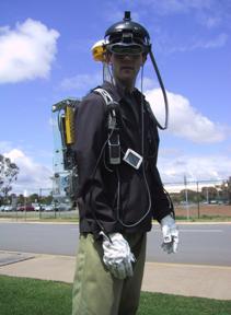 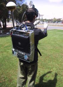
Figure 7‑3 Front and rear views of the Tinmith-Endeavour backpack in
use outdoors
|
The technology of the components for AR
research has been rapidly changing over the past few years and it is not
possible to keep a static design due to constant hardware upgrades. For
example, in the last two years video capture in laptops has changed from
analogue PCMCIA to USB, and now to 1394 Firewire. Most input devices are now
USB, although some legacy devices must still be supported with PS/2 and RS-232
ports. Merely placing all the items into a rucksack style container is not
possible due to the number of cables and various sizes and weights of the
devices. From my analysis, a rigid frame that the devices can attach to is the
best solution, as it allows enough flexibility to accommodate future changes,
even for unknown devices.
7.2.1 Previous designs
The original backpack shown in Figure 7‑2
is based on a hiking frame, containing aluminium pipes running along the sides
and across. Wooden back planes and straps are used to attach components but the
number of pipes to attach to is limited. Wires are routed using insulation tape
to hold them together and to the backpack, and requires cutting to remove and
leaves a sticky residue. The laptop is supported by a perpendicular wooden
plane at the bottom and then strapped to the backpack both horizontally and
vertically, and prevents access to the laptop without removing the straps.
While this design works, it is time consuming when problems occur or equipment
needs changing. A number of problems were identified from the previous backpack
designs during the requirements gathering process. Some of the problems
identified were:
· Hardware changes - Hardware is continuously improving and
reconfiguring components was difficult because many could only fit in certain
places on the hiking frame due to its shape.
Breakage
- Fragile connectors and cables were breaking easily because they were not
protected from external forces experienced when moving in the environment.
Travel -
The backpack was difficult to transport to overseas demonstrations due to its
size and fragility.
Fasteners
- Insulation tape was used to fasten cables and components, which leaves a
sticky residue.
Cable
bundling - Bundles of cables taped together are messy and waste space otherwise
available for other components.
Laptop
fastening - Straps holding the laptop in place prevented it from being opened,
making setup and debugging difficult.
Autonomous
operation - The cabling was so complicated it required an assistant to help
prepare the user for outdoor use.
Power
supply - Many devices contained their own power sources with different lengths
of operation, a centralised battery would simplify the operation of the
backpack.
7.2.2 Frame design
The new backpack design is worn by using
an industrial breathing apparatus frame. The frame is made of aluminium with a
foam padded interior and moulds to the contours of the body. The rest of the
system is contained within a clear polycarbonate moulded box with a pattern of
holes drilled over the surface, providing mounting points and air flow. The
polycarbonate box and frame are joined together with a hinge, allowing the
entire backpack to open into an A shape and be self supporting outdoors if
required. The polycarbonate box depicted in Figure 7‑4 is used to mount
all the components in, and a second box is mounted inside on a hinge to hold
the laptop - when the backpack is in the A shape, it is possible to fold the
laptop out like a table, as shown in Figure 7‑5. This design allows the
backpack to be placed on the ground outdoors to operate the laptop in a
traditional manner.
|
Figure 7‑4 Design of polycarbonate housing with hinged laptop holder
and internals
(Images
courtesy of ITD and SES – Defence Science Technology Organisation)
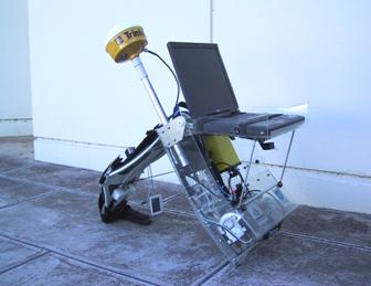
Figure 7‑5 Backpack shown in desktop configuration, permitting normal
use outside
|
7.2.3 Attachments
Attaching devices to the backpack is
difficult since many devices are manufactured with no mounting points and
little surface area to attach to or drill into. As a result, a variety of
strategies are needed to fix devices securely to the backpack. With the
previous designs, straps, double-sided tape, and permanent screw mountings were
used. The new interior design of the backpack is shown in Figure 7‑6,
with components fixed securely using Velcro and cables attached with cable
ties.
|
Figure 7‑6 Interior of backpack housing, showing internal components
and cabling
|
A special 3M developed Velcro is used as
the main means of attaching large components. This Velcro uses mushroom-shaped
plastic heads and four 1cm x 1 cm pieces can securely suspend the laptop
vertically. For safety, two straps run across the laptop keyboard are used to
protect it from falling if the Velcro were to fail. Components inside the
backpack also use Velcro but do not require safety straps because they are
lightweight and attached cables would provide support if the device detaches
during use. Using the Velcro enables easy rearranging of components as hardware
requirements change and small surface areas can support quite heavy objects.
Cables are run along the surface of the
polycarbonate in busses, with cable ties through the plastic grid holes to
secure them. This still does not truly solve the problem of easy configuration
since they must be destructively cut open when new cables are added or removed.
Since they are cheap, they are used in preference to insulator tape which does
not run well through holes and leaves a sticky residue. It would be desirable
to use some kind of reusable cable ties that can hold large bundles of wires
easily.
7.2.4 Power supply
Many of the components used require their
own battery, and so using a single dense power source means that all devices
run for the same amount of time. In the past, heavy lead acid 12V batteries
were used but these have been replaced with 12V Nickel Metal Hydride (NiMH)
batteries rated at 100 Wh. This battery powers all of the components except the
laptop for approximately 1.5 hours (varying depending on the equipment in use)
and may be swapped by an assistant while mobile. Linear voltage regulators are
used to run low current devices at 5 and 9 volts, as well as the Sony Glasstron
which uses a non-standard 8.4V. The Glasstron uses 1.2A of current at 60%
efficiency due to the linear regulators, but the additional cost and weight of
a DC-DC converter was not deemed necessary and instead spent on extra NiMH
batteries.
To distribute power, a specially designed
breakout box shown in Figure 7‑7 is used that has 8 four pin connectors,
each with GND, +5V, +9V, and +12V available. Devices may be easily plugged in
since one standard type of connector is used throughout the system (except for
the Sony Glasstron). Power breakout boxes may be chained if more sockets are
needed. A master power switch (with 5 Amp fuse and indicator light) is mounted
onto the front shoulder strap to allow the user to easily turn the power on and
off without having to remove the backpack.
|
Figure 7‑7 Power supply breakout box, with +5V, +9V, and +12V at each
connector
|
Figure 7‑8 depicts how the various
devices in the system acquire their power. Some devices are connected directly
to the breakout box while others receive it over their data bus connections.
|
Figure 7‑8 Power bus interconnect diagram of components used for
mobile outdoor AR
|
7.2.5 Connectors and cabling
|
Figure 7‑9 Two USB ports, glove connector, and cables mounted onto
shoulder straps
|
To make the system easy to use while
outdoors, a number of connectors are available on the shoulder straps to attach
devices to, as shown in Figure 7‑9. Four USB sockets are available on the
shoulder straps, allowing the user to plug in devices such as mice and
keyboards for debugging while mobile. Special Lemo connectors are used to
attach the 1394 video cable and IS-300 sensing cube, permitting the separation
of the HMD from the backpack. 8-pin sockets that attach to leads ending in
Mini-DIN connectors are used for the glove interface and are easy to plug in,
even while wearing the gloves. Since the 50-pin Sony Glasstron cable cannot be
cut for a connector, the entire unit is attached with Velcro so it can be
separated.
Internally, cables have been shortened
where possible to approximate lengths or tied into tight looms and cable tied
to the plastic grid on the backpack. The backplane allows many separate bundles
and so different subsystems are separated to allow changes without affecting
the rest of the cables. One risk of using tight cable ties is that they could
potentially damage fragile cables (such as the Glasstron 50-pin cable) if used
incorrectly.
7.2.6 Helmet
The Sony Glasstron HMD is a very fragile
device and has a limited surface area for attaching extra components such as
trackers and cameras. Rather than attempting to weigh down the small hinge on
the front of the HMD, the head band of the Glasstron is attached to a welding
helmet that has a semi-rigid plastic frame permitting attachments. The IS-300
sensor cube is mounted on the top of the helmet shield with plastic mushroom
Velcro, while the Firefly camera processing board is hidden underneath the
shield. The small CCD sensor for the Firefly camera is mounted onto the HMD
using a custom manufactured bracket with screws to adjust the angle, and a
flexible ribbon cable connecting it to the processing board. The helmet design
is depicted in Figure 7‑10, and photos were shown previously in Figure 1‑1
and Figure 7‑3. As mentioned previously, for demonstration purposes an IO-Glasses
HMD with Pyro 1394 camera is used and includes sufficient mounting space so
that an extra welding helmet is not required.
|
Figure 7‑10 Design of brackets to attach Sony Glasstron and Firefly
camera to a helmet
(Image
courtesy of ITD and SES – Defence Science Technology Organisation)
|
7.2.7 Transportation
Since this research is being conducted in
Australia, presentations at conferences usually require travel on airplanes.
Airlines are known to handle baggage very roughly and transporting delicate
computer equipment can be difficult. A special aluminium suitcase was designed
to transport the backpack, containing foam blocks that have been carved out to
fit the profile of the backpack. This foam is soft and protects the equipment
from shocks while being transported, reducing possible damage to the backpack
and improving reliability for demonstrations.
While the foam suitcase adequately
protects the backpack, the vibrations and other shocks experienced during
transport still manage to separate connectors and Velcro, requiring small touch
up repairs on arrival. Devices such as the laptop, GPS, IS-300, and HMD are too
fragile to be transported in this way and so are packed into a separate carry
bag as hand luggage. This bag has much thinner padding and is designed to fit
into the overhead compartment of an aircraft, with the assumption that the
person carrying it will properly handle the equipment.
7.2.8 Lessons learned
The new Tinmith Endeavour backpack is an
marked improvement over my previous backpack designs. Although this design is
better, there are still a number of areas where it could be improved that I
have discovered during development:
· Improve backpack frame design - The current breathing apparatus
frame comes in one generic size and is not designed to adjust for the different
sizes of people. This affects the weight distribution and for tall people means
that the weight rests entirely on the shoulders and none on the waist. This
fatigues the user very quickly and makes the backpack uncomfortable. By
replacing the breathing apparatus frame with an adjustable version this will
improve the ergonomics of the device and enable much longer operation runs.
Add more
ports to the shoulder straps - The USB ports on the shoulder straps allow easy
plugging in of equipment by the user while they are wearing the backpack. At
the time, 1394 connectors could not be purchased and so the camera cable was
split with Lemo connectors and run directly to the hub. With the new
availability of OEM 1394 sockets, these can now be embedded into the shoulder
straps easily.
With recent changes in some hardware
devices, it is also possible to streamline the backpack design further,
reducing its weight and power consumption:
· The InterSense InertiaCube2 can now be processed in the laptop, with
the InertiaCube plugging directly into the serial port. This removes the need
for the InterSense IS-300 processor that uses a large volume of the backpack
and large amounts of current.
The use
of new HMDs such as IO-Glasses means that no 8.4V conversion for the Glasstron
is needed, removing the need for inefficient power conversion and heat
dissipation.
The
embedding of RS-232 to USB chipsets into devices such as the glove controller
so that devices can draw power from the USB port. This removes the need for
large RS-232 cables and some of the power cables. If all legacy serial devices
can be removed it is then possible to remove the USB to RS-232 converter,
saving more space and power.
As the components in the backpack are
miniaturised over time, a redesign of the polycarbonate casing will eventually
be desired since unused space will accumulate.
As discussed in Chapter 5, the user’s
hands are the primary input device for the system. Finger presses as well as
the position of the hands provide the necessary inputs for the user interface
software. This section discusses how the gloves were constructed, the
electronic detection of finger pinches, and the implementation of position
tracking.
7.3.1 Glove design
Gloves have been used as input devices in
a large number of VR systems; they allow the use of the hands to interact with
the environment using natural pinch and grab style gestures. There are a number
of commercially available gloves on the market and these perform sensing in two
different ways: the FakeSpace PinchGlove [FAKE01] contains electrical contact sensors
at each fingertip to measure finger pinches, while the VTi CyberGlove [VIRT01] uses bend sensors to measure finger
positions. While full motion of the fingers may seem more accurate, errors in
the results make it difficult for software to determine exactly when the user’s
fingers are pressed together. Since my user interface requires only simple
finger press inputs, a design similar to the PinchGlove is the most desirable
as it detects accurate contact information. Although these gloves were
initially investigated for use in my user interface, they were disregarded
because the controller unit was too large and consumed too much electrical
power. As discussed in Chapter 5, I also wanted to experiment with the
placement of the metallic pads in various locations. For the purposes of my
research, I have created a number of sets of custom pinch gloves that allow
flexibility in working with different pad layouts. These gloves have conductive
pads that can be placed at any desired location, and use a small low powered
controller device suitable for use with a mobile computer.
The glove design is based on typical
fabric gloves available in many supermarkets and hardware stores, with wires
and connectors glued to the surface. The gloves are quite simple in operation
and rely on the completion of an electric circuit - conductive surfaces on the
fingers, thumbs, and palms detect when various pinch motions occur. Initially,
a partially conductive aluminium tape was used as the surface, but this did not
conduct well and was difficult to attach to the wires. Further improvements
used metallic wire wrapped and glued around the fingertips, giving improved
conduction and pinch detection but being more fragile. The latest design is
based around 3M copper adhesive tape, which gives the best conduction and is
also extremely robust. The three glove designs with aluminium tape, wire, and
copper tape are shown in Figure 7‑11.
|
Figure 7‑11 Designs of various versions of the glove and attached
fiducial markers
Shown
are aluminium tape, wire wound, and copper tape designs
|
Wires from the metallic surfaces are
attached to the glove controller box mounted inside the backpack via connectors
on the shoulder straps. The controller box contains a Basic Stamp BS2
microcontroller [PARA01] that uses very little power and is
fully functional in a small 24 pin IC sized package. The circuit depicted in
Figure 7‑12 connects the BS2 to the gloves with a minimal number of
components. The internal software applies voltage to each finger and polls for
which pad the voltage is detected on (thumb, palm, or none). If this value is
different from the last loop, a single byte packet is sent to the serial port
on the laptop for processing, containing the current status of the changed
finger. Since the microcontroller is dedicated to the task, there is no
overhead for the laptop and the polling can operate in a hard real-time loop at
30 Hz. As the design of the gloves changes, the controller can be upgraded by
downloading new firmware through the serial port.
7.3.2 Glove tracking
|
Figure 7‑12 Circuit schematic for the low power glove controller
|
The gloves are used to capture the 3D
position of the hands so the user can intuitively control the outdoor AR system.
As described in the background chapter, tracking in an outdoor environment
suffers from a number of known problems such as power consumption, size,
weight, and support infrastructure. The outdoor environment also contains harsh
conditions that cannot be controlled by the user. Some examples of these
problems are:
· Accelerometers cannot be used since they drift over time and the
registration of the cursor would be inadequate for accurate modelling tasks.
Infrared-based
systems are unreliable when used outside due to the large amounts of infrared
light given off by the sun.
Active
magnetic tracking relies on using large non-portable control units, consumes
large amounts of electric power, and would be affected by magnetic fields from
the equipment carried on the backpack.
One solution demonstrated outdoors was
the WearTrack system [FOXL00] by Foxlin and Harrington that
utilised ultrasonic technology. This system tracked the position of the user’s
hand relative to their head (with no orientation), and was used for a number of
interaction tasks. To implement this system, an ultrasonic tracker with its
associated weight, size, and electric power penalties must be added to the
wearable computer system.
The solution created for this
dissertation uses optically-based vision tracking. This approach allows me to
leverage the existing helmet mounted camera that is currently used for the live
AR video overlay. The ARToolKit libraries [KATO99] are employed to perform full six
degree of freedom tracking of the fiducial markers placed on the thumbs of the
gloves. Currently only the position values are used, as the accuracy of the
rotation values is not adequate. Implementing vision tracking with the gloves
simply requires the attachment of small and lightweight paper-based fiducial
markers, with no extra devices or batteries required. The paper markers used in
this implementation are 2cm x 2cm squares and are glued to the thumbs of the
glove. Another advantage of my vision-based tracking implementation is that
achieving accurate registration is relatively simple using the video from the
AR overlay.
|
Figure 7‑13 Example use of the fiducial marker tracking used for a 3D
cursor
|
7.3.3 Fiducial marker placement
It was initially proposed to put the
fiducial markers on the back of the user’s hands, but it was quickly realised
that the hands are large and fill much of the field of view of the camera. A
user would not be able keep the markers in the field of view and manipulate an
object to the edge of the display. The problem of accurately calculating the
user’s finger tip position based on fiducial markers on the wrists was also a
concern. It was decided that the index fingertips would not obscure the user’s
view, allow much finer motor control, and provide extended movement. The ends
of the index fingers were dismissed during simple trials however, as they moved
during menu option selections and would affect operations in progress. I did
however notice that the thumb only moved slightly during the pinch motion, and
the users studied tended to bring their fingers to meet their thumb as opposed
to moving the thumb to meet the fingers. The targets were then placed at the
tips of the thumb in an orientation that is fully visible to the camera when
the gloves are used for interaction and menu operations, as shown in Figure 7‑13.
7.3.4 ARToolKit calibration
The ARToolKit libraries [KATO99] were developed to support the
tracking of simple fiducial markers, allowing applications to appear to place
3D objects onto these markers when viewed on a display device – an example is
the ARToolKit simpleTest demonstration. While the ARToolKit generates
6DOF matrices for each fiducial marker, these matrices are expressed using a
special distorted camera frustum model and not usually in true orthogonal world
coordinates. If the calibration model for the camera is an accurate model, it
is possible to treat these camera coordinates directly as world coordinates. If
the calibration model for the camera is not perfect (the ARToolKit calibration
process does not always generate good results) then extra errors are introduced
during the conversion and it is unusable for tracking. I have developed a
method of correcting the calibration values so that the ARToolKit may be used
for tracking and inserting results into a scene graph [PIEK02f].
In applications that use ARToolKit as
intended (such as simpleTest), the video is first captured by libARvideo.
Next, recognition of fiducial markers and calculation of camera-space
transformations is performed in libAR, which is then used to render the
final scene using the camera calibration frustum in libARgsub. When a
pattern is recognised, a matrix transformation is returned from arGetTransMat(),
which defines the marker’s position and orientation (6DOF) relative to the
camera, in the camera’s calibrated coordinate system. The camera calibration
data is used by this function to modify the results to compensate for the
camera’s unique properties. Due to distortions in the camera and errors in the
calibration process, the coordinate system is not the typical orthogonal
coordinate system normally used in 3D graphics. If this camera-space matrix is
used to draw an object with libARgsub, the view frustum used in OpenGL
will be the same as that of the camera model, and so the image will appear to be
rendered at the correct location. An interesting side effect of these
transformations is that no matter how poor the camera calibration is, the 3D
object overlaid on the fiducial marker will always be correct since the
incorrect calibration model used in arGetTransMat() is reversed when
drawing using the camera as the view frustum in libARgsub. When the
matrix calculated in arGetTransMat() is put into a scene graph however,
errors occur in the output for two reasons. The first is that the camera
calibration is not being used to render the display and compensate for any
camera distortions. Secondly, if the calibration is not good enough and did not
model the camera accurately, further errors are introduced.
After calibration of a camera, ARToolKit
generates information for the camera similar to that depicted on the left in
Figure 7‑14. The values that define the coordinate system of the camera
(and also found to introduce the most errors) were the X and Y values for the
centre pixel of the camera and the other values in the matrix (highlighted with
boxes). In the default supplied calibration file, the Y axis is 48 pixels from
the centre of the camera but under testing I found most cameras had centres
that were reasonably in the middle. This was an error introduced during the
calibration process that requires correction before use, and forms the basis of
my calibration technique.
|
Figure 7‑14 ARToolKit default camera_para.dat file, with error x=2.5,
y=48.0
The
model is then corrected so the axes are orthogonal and usable as a tracker
|
The values generated by the ARToolKit
calibration procedure (as depicted in Figure 7‑14) are stored in a binary
file that can be easily modified. The technique is to adjust the highlighted
values but leave the focal point and scale values untouched because they are
reasonably correct and errors are less noticeable. The highlighted values are
replaced with the coordinates exactly at the centre of the display, with
320x240 being used for a 640x480 resolution camera. These changes are based on
the assumption that most cameras are straight and that any offsets in this
value are caused by errors in the calibration process and not in the camera
itself. Figure 7‑15 depicts the effects of these changes graphically,
where the original distorted camera is now orthogonal and suitable for use as a
tracking device in a scene graph. This technique is only useful for correcting
errors caused by the ARToolKit calibration with cameras that have the centre of
the image at approximately the axis of the camera. In distorted cameras, this
technique could produce results that are worse than the uncorrected version,
and so should be used with care and the results carefully monitored to ensure
that it is being used in an appropriate fashion.
|
Figure 7‑15 Graphical depictions showing original and new orthogonal
camera model
|
7.3.5 Tracking results
Although vision tracking may be CPU
intensive, the ARToolKit runs quite efficiently on the laptop and works
alongside the rest of the software with no noticeable problems. The 1394 camera
mounted on the user’s head captures the video for the video overlay and also
passes it to the ARToolKit subsystem for further processing. Dynamic lighting
conditions may cause problems for the tracking since the camera automatically
adjusts its settings for the overall image. Sometimes the resulting image may
be too bright or lacking enough contrast to produce the thresholded binary
image for the ARToolKit library to extract the fiducial markers, and so the
tracking fails. I intend on experimenting further with different cameras and
filters to help improve the ability to handle the bright and varying lighting
conditions outdoors. In dark twilight conditions, the tracker works quite
reliably due to the low light gathering capabilities of the camera, and a small
light attached to the HMD may be used in cases of complete darkness.
Although there are some problems, the
tracker is usually able to acquire the fiducial markers and provide tracking
information to the rest of the system. When used for 3D positioning the results
from the vision tracker is quite good and the registration is within the area
of the target. However, detecting 3D rotation is more error prone since large
changes in orientation only give small changes in perspective on the image,
resulting in very noisy output in the order of 20-30 degrees. As a result, I
currently only use ARToolKit for position tracking, providing a cursor for use
on the HMD. Chapter 5 described how by combining two cursors it is possible to
derive a high quality rotation using their relative positions.
Using ARToolKit as a general purpose
tracker with some adjustments has allowed me to integrate hand tracking into my
outdoor modelling applications that may otherwise have not been possible given
the conditions in the outdoor environment. Since the user interface described in
Chapter 5 has evolved to use only 2D position information, much simpler
tracking may be performed using algorithms such as blob detection. Coloured
balls with non-specular surfaces mounted onto the thumbs are much easier to
detect even under poor lighting, and would improve interactive performance and
tracking quality for the user.
This chapter has presented the hardware
components used to perform mobile outdoor AR and to support the applications developed
for this dissertation. The components used are mostly based on commercially
available devices since specific equipment designed for mobile AR is not
available. A new backpack named Tinmith-Endeavour was developed to provide a
flexible platform for the carrying of the required components outside. This new
design takes advantage of lessons learned over many years of backpack design
and is expandable to handle changes in the future. To provide input for the
user interface described in this dissertation, a new input device based on
pinch detecting gloves and fiducial markers was developed. Both the backpack
and gloves have been tested extensively and iteratively refined as part of this
dissertation research.
8
"The reward for work well done is
the opportunity to do more work"
Jonas Salk, MD
This dissertation makes a number of
significant and original contributions in the area of interactive 3D modelling
for outdoor augmented reality environments. The contributions described in this
dissertation can be summarised as the development of augmented reality working
planes, construction at a distance techniques, user interface technology, and
the software and hardware needed for implementation. These contributions have
been demonstrated with real world examples and provide the capability to
perform modelling of 3D geometry in outdoor environments. With these
contributions there are a wide range of future possibilities for new research
and applications that may be used in scientific and commercial settings.
Seven unique contributions to the area of
computer science are described in the following sections. These contributions
form a solution to the problems associated with interactive 3D modelling in
outdoor augmented reality worlds. The introduction to this dissertation
contained a set of six research questions and three research goals. The seven
contributions answer each of these questions, providing a practical and
demonstrated solution for each one. Each of the goals outlined were used as
principles during the development of these contributions and guided their
development.
The ability of a human to perceive depth
information attenuates rapidly as the distance increases. Most existing
techniques for virtual environments are designed to operate within arm’s reach
and so different techniques are required for interacting with objects at large
distances. Outdoor objects such as buildings are very large compared to the
size of a human and are beyond their depth perception, even if a part of the
building is within arm’s reach. By thinking of distance as sideways motion from
a different view point, it becomes possible to avoid problems with inaccurate
depth perception. The augmented reality working planes technique is developed
based on existing concepts used in CAD modelling systems. By creating an AR
working plane at a distance from the user, vertices may be projected against
this surface from any distance with no reliance on the depth perception of the user.
AR working planes may also be defined and used to manipulate existing objects,
providing a complete set of modelling interactions. AR working planes have an
accuracy which attenuates at a constant rate that is better than human depth
perception, and is limited only by the resolution of the pixels on the HMD and
the tracking devices in use. The concept of AR working planes encompasses a
number of ways to create the planes, and may be made relative to the various
coordinate systems the user is familiar with. By taking advantage of the
alignment of landmarks that can accurately position a user, AR working planes
may be created that are aligned with physical world objects. The flexibility of
AR working planes may be used to perform a wide variety of modelling operations
and forms a basis for the next contribution. A further advantage to the use of
AR working planes is that only 2D input devices are required, which makes the
implementation much easier using currently available mobile hardware.
A naïve way to perform outdoor modelling
is to create each vertex by hand and then connect them together to form
polygons and objects. This method is time consuming and does not take advantage
of the many properties of outdoor objects that can be used to minimise the
amount of data entry required. Humans are quite capable of understanding the
design of objects around them and this knowledge is used to break down the
modelling of a building into a set of simple and much higher-level steps. For example,
instead of specifying vertices directly, the user may project walls aligned
with the object and the system can calculate the vertices and polygons
automatically based on the intersection points. This dissertation presented a
collection of techniques named construction at a distance that provides the
ability to perform various modelling operations. By iteratively combining these
techniques, complex shapes may be formed. Using an AR preview the user can
construct the model in steps and compare it against the physical world,
iteratively refining the parts that need the most work according to the
judgement of the user. The construction at a distance techniques have been
demonstrated with examples performing the modelling of many complex outdoor
shapes.
There are only a small number of user
interfaces for mobile AR and many of these are quite simple and use existing 2D
desktop metaphors. With AR focusing on the use of the body as an input device
to view information, little research has been performed into performing
higher-level interactions such as those required for 3D modelling. A further
complication is that tracking technology for mobile computers suffers from
problems not normally experienced indoors, and so this must be taken into consideration
with any interface design. Command entry is required to select amongst the
number of different AR working planes and construction at a distance techniques
available. Furthermore, these techniques also require pointer-based
interactions to create vertices and perform manipulation operations. This
dissertation describes a user interface designed specifically for mobile AR
applications, based on the user’s hands. By using the mapping of finger pinches
to commands, the user may execute commands without using the cursor, leaving
the hands available for pointing-based interactions. Keeping command and
pointing actions separate allows both actions to be performed simultaneously if
desired. To complete the AR user interface, a wide range of information is
presented to the user so they understand the state of the application and the
environment around them. By using external VR style views, the user is able to
see information not normally visible from the immersive AR view. The design of
this user interface was iteratively tested in small informal user studies to
find design flaws and then make improvements.
There are a small number of input devices
that are suitable for use with mobile computers because of limitations imposed
by the outdoor environment. Most 3D tracking technology is not suitable for
mobile computing but is also not required since AR working planes only requires
a 2D input for a cursor. Existing desktop input devices such as trackballs and
joysticks may be difficult to operate since there are numerous levels of
indirection applied between the user and the task. Since operations are
performed against AR working planes, the direct motion of the hands is used as
an input device. Instead of manipulating a cursor indirectly, the user can
simply reach out and point directly at the plane to perform operations. This
dissertation presents a vision-based tracking system to support the user
interface with intuitive hand-based control. Simple metallic sensors are used
to detect pinching motions, and are mapped directly to the menu system.
Fiducial markers mounted on the thumb are tracked using the HMD camera
providing video overlay, and operates in a wide variety of lighting conditions.
This hand tracker is a simple and yet very effective input device for mobile
outdoor AR, requiring no major extra equipment not already included in the
system.
This dissertation presents applications
that have been developed using the other previously discussed contributions.
The Tinmith-Metro modelling application demonstrates the use of AR working
planes and construction at a distance techniques, controlled by the user
interface and vision tracked gloves. This application implements all of the
examples presented in this dissertation, with the goal being to produce a tool
that may be used to create and capture the geometry of outdoor structures. The
examples are used to demonstrate the capabilities of the techniques described
in this dissertation.
Software toolkits for 3D virtual
environments are not sufficiently developed to the point where applications may
be developed by simply connecting together various components. In 2D desktop
environments, simple toolkits were built and then used to perform research into
increasingly higher-level tools. Current 2D toolkits are extensive and do not
require the programmer to perform very simple operations since a best practice
has been developed for many types of tasks. In contrast, 3D toolkits are much
less mature and only simple tasks such as tracker abstraction have reached a
best practice. The developer of 3D applications is currently required to
implement many of the features that an application needs. Existing software was
not adequate for the implementation of the contributions of this dissertation,
and so a number of new solutions were developed to current problems. This
dissertation contributes to the existing body of work by developing a software
architecture with a number of novel features such as an object-oriented design
based on data flow, a file system approach for an object store, and a
streamlined and high performance implementation. This software architecture
forms a basis for the applications developed for this thesis, and made the
implementation much simpler than would have been possible by attempting to use
a collection of existing tools.
Most of the equipment used for the
development of AR systems is based on commercially available components, but
these must be modified since the components are not normally designed for
mobile and outdoor requirements. In other cases, components that can not be
purchased must be designed and constructed. Since the desired task is mobile
outdoor AR, all the equipment required must be worn by the user. Integrating a
number of components into a system that can be worn outdoors is non-trivial,
and must take into account restrictions such as weight, size, power
consumption, mounting, and capabilities. This dissertation contributes a design
for a mobile backpack computer that uses a flexible internal architecture to
carry a number of devices while also being easy to change. Since hardware is
constantly evolving, the ability to accommodate these changes is important when
performing research with mobile AR systems.
With the availability of 3D modelling
techniques for use in mobile AR environments, a wide range of possibilities for
future work are available. I would initially like to explore possible
applications where the 3D modelling techniques can be used to enhance existing
work. As mentioned in Chapter 2, there are a number of techniques currently
used to capture the physical world but they have some limitations, and my
contributions address some of these. It would be interesting to explore how the
modelling techniques may be integrated with existing capture techniques to
provide real-time feedback using AR and allow interactive changes. Chapter 4
discussed how the modelling techniques may be used to create geometry for
objects that do not exist yet. This capability would be useful for landscape
designers and architects to plan the construction of new developments while on
site. When I have discussed my research with various people, I have received
much interest from people in areas such as architecture, construction,
forestry, gaming, surveying, and visual arts who are interested in trying the
technology for their particular applications.
There are a number of areas I would like
to perform further research in to improve the contributions made in this
dissertation. Hardware is continuously improving and this increases the
features that can be implemented. It would be interesting to combine the
construction at a distance techniques with existing image-based reconstruction
algorithms, so that the system can automate simple tasks while still giving the
user control over the process. As discussed previously, the use of speech
recognition technology would be a very useful addition to the user interface in
Chapter 5. Using the distributed software architecture described in Chapter 6,
applications can be developed that support users on multiple systems (both
indoors and outdoors) to collaborate on various modelling tasks. It would be
interesting to explore collaboration tasks further to find out the types of interactions
that are useful when working in these environments. With the availability of a
reference platform, the development of user studies to test future improvements
is now possible, and verifying which techniques perform the best in this
environment would be useful – the current design is based on knowledge from the
VR area that may not fully apply. For the technology to progress towards
mainstream use, it will require all the components to be better integrated and
miniaturised. I would like to explore the use of smaller computers such as hand
helds and tablet PCs as replacements for the laptop, with the goal being to
reduce the current backpack to something more manageable and that may one day
fit into the user’s pocket.
When this dissertation was written, the
goal was to create the necessary user interfaces and techniques required to
perform 3D modelling. While this goal has been achieved, the modelling
application now needs to be used to solve real world problems in order to be
useful. To allow the ideas in this thesis to mature into applications that can
be used in the real world, I have formulated a scenario which is both useful
and can be used to thoroughly test out future developments. The scenario is of
a disaster recovery system, to be used by rescue workers when areas of cities
have been destroyed by an event such as an earthquake. A current problem with
these cases is that workers may not know what the landscape looked like
previously, and therefore they may not know where to dig and search. Using
previously captured models overlaid onto the landscape, the previous
environment is made obvious to the wearer. The AR equipped rescuers can then
direct other traditional rescuers to places of interest, even in conditions of
dust or darkness. Another important problem with rescue efforts is coordination
amongst workers. Trying to communicate spatial information about the
environment to another person on a radio is quite difficult, especially when
there is confusion and panic. Using AR, the user is able to mark up the
environment around them and perform tasks such as highlighting damaged walls
and unsafe areas, modifying building models in 3D to reflect changes, and
adding virtual post-it notes and warning signs. These changes can be shared
with other users over a wireless network, and also communicated back to the
operations managers at headquarters to increase their situational awareness.
These operations managers are responsible for controlling the entire effort,
and giving them the ability to see information gathered in real-time would help
them better understand the situation and use resources effectively. Apart from
just gathering information though, the operations managers also have the
ability to modify the information and add markers to the environment to guide
the mobile users. This could be used to indicate places to visit or avoid based
on the combined knowledge of all the participating users. For this scenario, I
envisage the various participants will be using numerous types of technology
depending on what is appropriate for the task. For example, outdoor users may
wear full AR systems or carry hand held computers. Indoor users may use desktop
monitors, large wall displays, or projector tables with tangible interfaces. I
think that making all of these different technologies work together to solve a
difficult problem is the next big step, with many benefits to society as a
result.
Research in the area of outdoor AR environments
is still in its infancy. This dissertation has provided a number of
contributions to the area but there is still much research to be performed
before AR applications will become mainstream. This is an exciting time to be
working in the field, with many currently untouched problems that remain to be
solved and so many exciting possible applications. I hope that in the near
future it may be possible to realise a mobile AR system that can be used both
indoors and outdoors, fits into the pocket, works all the time without
reliability problems, and provides a real sense of presence for the virtual
objects overlaid onto the physical world.
A
"Men have become the tools of their
tools"
Henry David Thoreau (1817-1862)
Appendix A - Evolutions
During the research for this
dissertation, wearable computers have evolved from very simple and slow 2D
graphics to highly detailed 3D rendering systems capable of video overlay,
texture mapped triangles, and the ability to render millions of triangles per second
for realistic AR output. As discussed in the previous chapter, this evolution
process is ongoing as various devices are improved by their respective
manufacturers. This appendix discusses the numerous mobile outdoor AR systems
that I have constructed at key points in their development, broken down into
the equipment that was used, how it was mounted onto the user, and the software
that was developed for the platform. Since these three categories were not all
changed at the same time (the same software may have been used with multiple
types of equipment), platforms are described at various important milestones of
development.
A.1 Map-in-the-Hat (1998)
The first prototype system I worked on
the development of was named Map-In-The-Hat [THOM98] [PIEK99a], with the objective being to
develop a mobile navigation system that could guide users towards waypoints in
unfamiliar terrain. This system could also be referred to as the Tinmith-I
prototype since further designs were named after this, although it was never
referred to in any literature using this name. Although the computer used was
designed for mounting on a belt, there were too many components to carry and so
a ruck sack was used instead. While this system was used for several informal
studies, the wearable computer had faulty video hardware that caused it to run
very slow, and the GPS did not reliably receive satellite signals.
A.1.1 Equipment
|
Figure A‑1 Phoenix-II wearable computer with batteries, cables, and
belt mounting
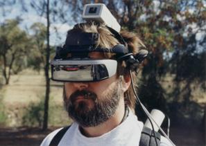 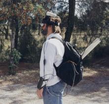
Figure A‑2 Map-in-the-Hat prototype inside
ruck sack, with antenna, cables, and HMD
 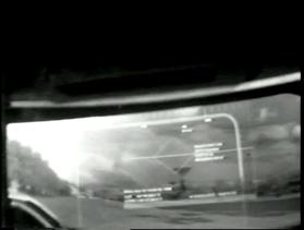
Figure A‑3 Screen shots of Map-in-the-Hat indicating a waypoint on the display
|
An initial collection of equipment was
supplied by DSTO and was used for this initial evaluation. This initial
equipment included the following:
· Phoenix 486 belt mounted wearable computer (16 mb
memory, 500 mb hard drive, 640x480x4bpp VGA output @ 2 Hz - see Figure A‑1)
Precision
Navigation TCM2 magnetic compass (15 Hz updates)
Trimble
SVeeSix GPS with radio-based differential receiver (1 Hz updates at 5-10 metres
accuracy)
Sony
Glasstron PLM-100 NTSC resolution HMD with optical overlay
Phoenix forearm keyboard for data entry
12V lead
acid batteries rated at 14 Wh
A.1.2 Mounting
A simple ruck sack was used to carry all
the components on the user’s back, as shown in Figure A‑2. This ruck sack
did not organise the components inside and so was difficult to work with. Some
issues associated with this ruck sack design are:
· Components are placed arbitrarily into the sack
Equipment
moves around due to non-rigid mounting
Cables
and connectors break easily due to movement inside backpack
Not
possible to get easy access to components or wires
A.1.1
Software
The software for this initial prototype was
quite primitive and was not implemented with a software architecture. The
application was a simple X11 program written for Linux that processed the
compass and GPS inputs to draw a steering gadget onto the display. The optical
overlay capability of the HMD was used to produce the final AR view of the
world. The steering information was a diamond that overlaid the destination
target along with bearing and distance values, as shown in Figure A‑3.
This prototype was useful for discovering problems with the numerous components
being integrated, and the knowledge gained was used for the development of
future systems.
A.2 Tinmith-2 prototype (1998)
After the experience from Map-in-the-Hat
a new system was designed from the ground up for the purpose of performing the
mobile navigation task much more effectively. Instead of just providing simple
navigation cues, this software was designed to support both 2D maps and 3D
immersive wire frames with optical overlay [THOM99]. This version is implemented using
a flexible software architecture [PIEK99b] designed to be extended for other
tasks in the future. Later systems use this software architecture for the
development of other applications. This version is named Tinmith-2, and there
was no version one because this was reserved for the previous Map-in-the-Hat
system. The name Tinmith was originally coined based on an abbreviation for “This
Is Not Map In The Hat”, although is never referred to in this way.
A.2.1 Equipment
|
Figure A‑4 Tinmith-2 hiking frame with some equipment attached
|
The equipment for this version was similar
to the last, except the wearable computer and GPS were both replaced to improve
reliability. The laptop had the added benefit of providing an LCD screen and
keyboard to enable simple debugging while outdoors. The following equipment was
added:
· Toshiba CDS320 Pentium-200 laptop (64 mb memory, 2 Gb hard drive,
800x600x16bpp 2D VGA with C&T 65555)
Garmin
GPS 12XL 12 channel hand-held receiver with radio-based differential receiver
(1 Hz updates at 5-10 metres accuracy)
A.2.2 Mounting
The carrying sack was replaced with a
rigid frame (see Figure A‑4) that allowed much more stable attachment of
the components to the backpack. This frame also permitted much greater access
to the equipment and made debugging much easier for development. Some
properties associated with this mounting are:
· Hiking frame with aluminium rails to attach components
Small
amount of reasonably light equipment
Easy
access to all equipment and wires, improving visibility and debugging
Objects
held with packing tape and gravity assisted to hold in correct position
Laptop
contained within a cardboard box strapped to hiking frame with packing tape
HMD
controller not mountable and placed in the pocket of the user
Design
not robust enough since the tape would gradually unattach from the frame
A.2.3 Software
|
Figure A‑5 2D top down map overlaid on physical world (using offline
AR overlay)
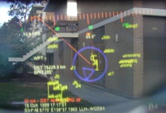
Figure A‑6 2D top down map overlay with current location relative to
nearby buildings
|
This application performed a similar
navigation task as Map-in-the-Hat, but instead used a top down view with a
steering arrow (see Figure A‑5 and Figure A‑6) to indicate the
direction to walk in while at the same time showing a line drawn map of the
area with other waypoints [PIEK99b]. This arrow was much more
efficient to use since it was not limited to the field of view of the HMD; the
previous steering diamond could not indicate to the user the orientation of an
object that was to the side of or behind the user. Using the forearm keyboard
the user may mark new waypoints and control the information displayed. An
immersive 3D wire frame display (see Figure A‑7) was also developed so
that models could be overlaid onto buildings, and this was used to visualise
simple extensions to buildings in the physical world [THOM99]. Since the video hardware supported
only 2D acceleration, wire frame rendering and optical overlay was used to
minimise load on the CPU. This software also contained an internal architecture
that allowed various software modules to perform different tasks and then share
data over an internal bus. By separating the software into modules it can be
easily distributed across multiple machines, supporting distributed processing
and monitoring by outside computers on a network. This distribution capability
was useful when there were not enough serial ports on the Toshiba laptop, and
the Phoenix-2 was used to provide an extra RS-232 serial port processed by a
software module and then sent to the main laptop.
|
Figure A‑7 3D wireframe overlay of building, with small extension made
to the left
|
A.3 Tinmith-3 prototype (1999)
For the Tinmith-3 prototype the existing
software was extended so that it was able to share information with other
wearables and indoor computer systems. Using the DIS protocol [IEEE93], various software applications may
render views of both physical and simulated entities, and provide situational
awareness to wearable and fixed users [PIEK99c]. The backpack was reconstructed to
use rigid mountings and straps instead of the fragile packing tape, greatly
improving its reliability.
A.3.1 Equipment
The equipment for this prototype was the
same as the previous Tinmith-2, except the Phoenix-2 wearable computer
providing the extra serial port was removed. The following components were
added:
· Quatech 4-port PCMCIA serial adaptor
Lucent
WaveLAN PCMCIA wireless network card
A.3.2 Mounting
|
Figure A‑8 Tinmith-3 backpack with HMD, head tracker, and forearm
keyboard
|
The previous backpack using packing tape
was rebuilt to use a more permanent and fixed design that was much more
reliable, and is shown in Figure A‑8. Some properties of this new fixed
design are:
· Same hiking frame as previous
Wooden
panels hold devices that cannot mount directly to the frame, fixed with screws
and straps
Panels
held using metal brackets allowing some limited rearrangements
Frame is
an awkward curved shape to mount to
HMD
controller not mountable and placed in the pocket of the user
Laptop
cannot be opened and used since it is tightly strapped up
Much
more rigid, safer, and reliable design
A.3.3 Software
The same software architecture from
Tinmith-2 was used, except various extensions were added to capture data from
DIS protocol-based simulation software and present it to the display module,
with tracking information broadcast back to other DIS simulation software.
Figure A‑9 depicts the layout of all the modules in the system, with the
lsapdis and tracker modules providing the extra interfaces for this support.
Tinmith-2 contained the same modules and layout except for these two extensions.
|
Figure A‑9 Software interconnect diagram for Tinmith-2 to Tinmith-4
prototypes
|
|
Figure A‑10 View of ModSAF tool with simulated entities and a wearable
user
|
To demonstrate the system, the ModSAF
tool (see Figure A‑10) is used to generate a set of simulated helicopters
that fly across a virtual landscape according to a set of rules created by the
simulation manager. The display for ModSAF can show the locations of entities
it is simulating, as well as any entities generated by other computers, from a
top down 2D control panel. The wearable user located outdoors (see Figure A‑11)
generates DIS packets that are then displayed as another entity in ModSAF. For
a VR style view, the MetaVR application is capable of rendering DIS entities
onto a 3D landscape, with views such as Figure A‑12 showing an avatar of
the wearable user observing a ModSAF simulated helicopter. On the AR HMD of the
user, both of the previously discussed 2D top down and 3D immersive views may
be used to display points and labels representing the entities simulated by
ModSAF or generated by other wearable computers. The 2D view shown in Figure A‑13
is the wearable’s top down HMD view of the simulated entities in the previous
figures.
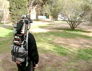
Figure A‑11 Wearable user in outdoor environment generates DIS packets
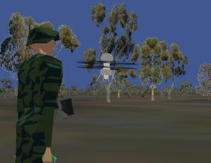
Figure A‑12 MetaVR view of avatar for wearable user and helicopter for
ModSAF entity
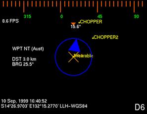
Figure A‑13 DIS entities overlaid in yellow on HMD with a top down view
A.4 Tinmith-4 and ARQuake prototype (1999)
The Tinmith-4 prototype was extended to
develop two new applications. The first was an architectural visualisation
application, where filled triangles can be rendered to the display to present
to the user more realistic looking models. The game Quake was also modified to
produce a new AR version named ARQuake [THOM00] [PIEK02d], using the Tinmith-4 software to
provide position and orientation information about the user. These were the
last applications developed using the current software architecture before it
was replaced with a rewritten version.
A.4.1 Equipment
Same as the previous Tinmith-3 prototype
A.4.2 Mounting
Same as the previous Tinmith-3 prototype
A.4.3 Software
The architectural visualisation application
was developed by rewriting the previous display module with a new 3D renderer,
capable of drawing filled depth sorted triangles instead of just simple wire
frames. Numerous optimisations were performed to make the rendering possible on
the hardware available, and the complexity of the models was limited to a few
hundred polygons to keep reasonable frame rates. Models were converted from
AutoCAD DXF files and loaded in, allowing architects to preview the models
designed on desktop software with outdoor AR systems, as shown in Figure A‑14.
|
Figure A‑14 Visualising artificial CAD building extensions overlaid on
physical world
|
The ARQuake application was developed
using the GPL released Quake source code from ID Software [IDSO01], and is a first person shoot-em up
game so it has a view point similar to a VR system. When operated on an optical
overlay HMD, objects in the game appear over the physical world, as shown in
Figure A‑15. Instead of using a keyboard or mouse to control the game, it
was modified to use the position and orientation sensors on the body as an
input device. An extra software module was written using the Tinmith
architecture that generated UDP packets for ARQuake based on the tracker values
available. Using a custom haptic feedback gun, the user may attack monsters
using a highly intuitive trigger input that most users are familiar with. Since
the game does not support individually aimed weapons, the gun is not tracked
and the user aims with their head.
|
Figure A‑15 ARQuake implemented using optical AR with virtual monsters
shown
|
A.5 Tinmith-evo5 prototype one (2001)
Although the previous software
architecture was quite powerful, it was optimised for the navigation task and
the use of older equipment. With the arrival of hardware accelerated OpenGL and
faster CPUs, I wanted to start doing research into complex 3D modelling tasks
involving input gloves, vision tracking, and live video overlay. The goal was
to produce an interactive modelling system that used intuitive hand gestures to
control the environment, with an artistic impression shown in Figure A‑16.
The capabilities desired were out of the scope of the original software
architecture and so a new one was designed to be the platform for all my future
AR application development. This prototype was used to implement my first
demonstrations of street furniture and infinite planes modelling in AR [PIEK01b] [PIEK02c].
|
Figure A‑16 Mock up demonstrating how a modelling system could be used
outdoors
|
A.5.1 Equipment
For this update almost all of the equipment
was replaced since the previous equipment was becoming quite outdated. The
equipment added was as follows:
· Gateway Solo Pentium-II 450 laptop (64 mb memory, 6 Gb hard drive,
1024x768x24bpp OpenGL with ATI Rage Mach64)
CPIA
chipset-based USB camera (352x288 frames at 5 Hz)
Custom
designed pinch gloves with metallic pads and low power microcontroller
interface
Glasstron
PLM-700E 800x600 resolution HMD with opaque settings for video AR
LCD
television rendering live video overlay previews for bystanders to observe
during demonstrations
InterSense
IS-300 hybrid orientation sensor (100+ Hz updates)
Trimble
OEM Ag132 GPS with Omnistar satellite differential receiver (10 Hz updates at
50 cm accuracy)
12V lead
acid batteries rated at 85 Wh
A.5.2 Mounting
Similar mounting techniques as previous
were used for the newer components, and due to the increased complexity of the
design this backpack began to become unwieldy, as seen in Figure A‑17 and
Figure A‑18. This was the last prototype to use the current backpack
before the switch to the new Tinmith-Endeavour design. Some properties of the
current design are:
· Component count larger due to increased functionality (TV output,
cameras, gloves)
Cabling
complexity increased due to extra equipment
Connectors
fitted to waist holders for attaching devices while mobile
Not all
devices fit the wooden panels and curvature of backpack frame
Difficult
to add extra devices without moving all existing equipment around
Sony
Glasstron was still not mounted, held with a strap around the neck
|
Figure A‑17 Side view of original Tinmith-evo5 backpack, with cabling
problems
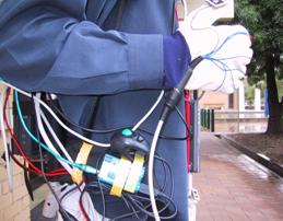 
Figure A‑18 Close up view of messy cable bundles and miscellaneous input
devices
|
A.5.3 Software
This version uses a completely rewritten
set of software designed to perform the modelling tasks envisaged [PIEK01c] [PIEK02a] [PIEK03f]. The implementation was described
previously in Chapter 6, and is written in C++ and uses a much more efficient
model for processing data. Using an object-oriented approach, each object
contains data that can be listened on for changes by other objects in the
system. Since all the components of the application are written using this
software architecture, everything is tightly integrated and consistent. A user
interface based on cursors mapped to the user’s thumbs as well as a menu system
was implemented to support complex modelling tasks such as CSG and 3D
manipulation. The modelling tasks implemented were simple versions of the
infinite planes and street furniture techniques described previously. This
first prototype (with video overlay AR output shown in Figure A‑19) was
mostly used for experiments in testing out initial modelling techniques and
gathering information for the development of later improved versions.
|
Figure A‑19 Screen shots of the first Tinmith-Metro release in use
outdoors
|
A.6 Tinmith-VR prototype (2001)
As part of informal user experiments
described in Chapter 5, I wanted to test the usefulness of the user interface
in an indoor VR environment [PIEK02b] [PIEK02e]. Since the interface is relatively
generic it may be used in VR systems with only slight tracker changes. The
hardware used was similar to typical VR systems, with a Polhemus magnetic
tracker and opaque HMD used indoors, as shown in Figure A‑20.
A.6.1 Equipment
This system did not use a backpack
computer and instead used indoor-based hardware to render to the VR display.
The components used were as follows:
· Dell Inspiron 8100 laptop with Pentium-III 1.2 Ghz (512 mb memory,
40 Gb hard drive, 1600x1400x24bpp OpenGL with NVIDIA GeForce2Go)
Polhemus
magnetic tracker with 3 sensors
Daeyang
Cyvisor 800x600 resolution opaque HMD
Power
supplied from 240 volt mains supply
Custom
designed pinch gloves with metallic pads and low power microcontroller
interface (no vision tracking)
A.6.2 Mounting
Since the equipment was used indoors and the
user has a limited working range, everything was mounted to various parts of
the room. Some properties of this mounting are as follows:
· One Polhemus magnetic sensor was mounted on the HMD to track head
motion
Two
Polhemus magnetic sensors were mounted onto the gloves of the user, replacing
the vision tracking system
User is
tethered to the system via a cable bundle attached to the ceiling
Reliable
and easy to configure since the environment is fixed
|
Figure A‑20 VR immersive system used to control the Tinmith-Metro user
interface
|
A.6.3 Software
The same modelling software previously
described was modified to produce a VR version for use indoors, with a small
example world shown in Figure A‑20. The video overlay was disabled,
software reconfigured to use the Polhemus trackers, and extra features added to
support the VR nature of the system. The same interface involving a cursor and
menus was used to control the application, and users experienced with the
outdoor system could use exactly the same interaction techniques to control the
indoor system.
A.7 Tinmith-evo5 prototype two with Tinmith-Endeavour (2002)
For this prototype, all of the lessons
learned from previous versions were used to redesign both the hardware and the
user interface techniques. Although using similar equipment to the previous
prototype, a new backpack frame was designed with DSTO for the specific purpose
of being used for outdoor AR. The user interface was redesigned and simplified
to make modelling tasks for the user easier, and a number of new construction
at a distance techniques were added to supplement the previous techniques. Many
of the techniques discussed in this dissertation are implemented in this
prototype.
|
Figure A‑21 Side and front views of the Tinmith-Endeavour backpack in use
outdoors
|
A.7.1 Equipment
Along with the new backpack design, a
newer and much more powerful laptop was introduced that is capable of rendering
live video overlay texture maps for AR at interactive frame rates. By using
newer and higher resolution 1394 Firewire cameras, the quality of the video is
improved dramatically from previous prototypes and produces much more
compelling demonstrations outdoors. The new components used are as follows:
· Dell Inspiron 8100 laptop with Pentium-III 1.2 Ghz (512 mb memory,
40 Gb hard drive, 1600x1400x24bpp OpenGL with NVIDIA GeForce2Go)
Point
Grey Research Firefly 1394 camera (640x480 frames at 15 Hz)
Trimble
Ag132 GPS with Omnistar or radio differential receiver (10 Hz updates at 50 cm
accuracy)
Custom
designed pinch gloves with wire wound pads and low power microcontroller
interface
A.7.2 Mounting
This prototype introduced the new
backpack design from DSTO [PIEK02h], which was discussed previously in
Chapter 7 and shown in Figure A‑21. Due to the flexible design of the
backpack, components can be mounted in a number of configurations and easily
changed. The following features are available with this backpack design:
· Using Velcro attachments, components can be easily rearranged
Cabled
fixed internally with cable ties to prevent movement
Hinged
design allows laptop to be used on a horizontal surface while outdoors
Laptop
screen held open to permit bystanders to see live AR video overlay
Connectors
and switches mounted on shoulder straps for easy access
New
helmet design to mount cameras and trackers onto HMD
A.7.3 Software
The software architecture for this system
is similar to the first Tinmith-evo5 prototype, except that improvements were
made to improve the implementation of internal objects, speed up performance,
and extend the serialisation mechanism to use it for distributed indoor/outdoor
collaboration tasks. The user interface was improved based on the informal user
studies discussed in previous chapters [PIEK03d], making it more intuitive and
efficient to control the system with. While the previous prototype only
implemented a small number of outdoor modelling techniques, this new version
implements many of the construction at a distance techniques described in this
dissertation [PIEK01b] [PIEK02g] [PIEK03c]. This version contains the most up
to date demonstration of the techniques in this dissertation.
|
Figure A‑22 Screen capture of the latest Tinmith-Metro release in use
outdoors
|
A.8 ARQuake prototype two with Tinmith-Endeavour (2002)
The previous Tinmith-evo5 prototype two
used for outdoor AR modelling tasks is also able to run the modified ARQuake
game discussed previously. For this version, the software was updated to use
the latest Tinmith-evo5 software architecture and configuration system,
supporting the latest equipment with improved accuracy and performance. The
main noticeable improvement was the use of the GLquake source code with OpenGL
acceleration and a video-based AR overlay modification to greatly improve the
quality of the output [PIEK03a].
A.8.1 Equipment
Same as the previous Tinmith-evo5
prototype two, with an extra input device for ARQuake. The haptic feedback gun
was replaced with a much simpler USB-based version that draws less power and
looks more like a toy, as shown in Figure A‑23.
|
Figure A‑23 USB
mouse embedded into a children’s bubble blowing toy
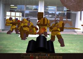 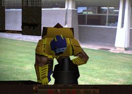
Figure A‑24 Monsters overlaid on the physical
world with video overlay ARQuake
|
A.8.2 Mounting
Same as the previous Tinmith-evo5
prototype two
A.8.3 Software
The ARQuake software described previously
was rewritten to use the new Tinmith-evo5 software architecture, which is both
more efficient and supports more types of tracking devices. The type of AR
implemented was also changed from optical to video overlay, similar to the
latest Tinmith-evo5 software. OpenGL stencil buffers were used to overlay a
video texture onto the areas that were black in the original optical version.
The final result is excellent image quality with vivid colours and sharp edges
well suited for demonstrations, as shown in Figure A‑24.
A.9 Summary
This appendix has presented the history
and evolving nature of the hardware and software developed as part of my
research into outdoor AR. While the quality of the first AR systems was
initially quite primitive with limited functionality, the latest AR systems are
capable of performing complex 3D modelling tasks with displays that are much
more compelling for the user.
B
"Reality is merely an illusion,
albeit a very persistent one."
Albert Einstein (1879-1955)
Appendix B - Attachments
This dissertation has resulted in the
production of a large quantity of pictures, videos, and other support
information that is not included with this thesis. Some of this material is
contained on a CD-ROM produced at the time of the publication of this
dissertation, while other up to date information is available on the Internet.
B.1 CD-ROM
The attached CD-ROM contains electronic
copies of the following material:
· Copy of this dissertation, both as a whole and separated by chapter
(PDF)
Archive
of all conference and journal papers published to date (PDF)
Videos
demonstrating the modelling applications in use outdoors (MPEG1)
Videos
demonstrating applications discussed in the evolutions appendix (MPEG1)
The documents in PDF format require the
use of Adobe Acrobat Reader or Ghostscript to view or print the files. Acrobat
Reader is available free from http://www.adobe.com
and Ghostscript is included with most free operating systems such as Linux,
FreeBSD, and Cygwin. The videos are encoded in MPEG1 format, and should be
viewable using most video playback software available in the last five years.
MPEG1 files are known to playback on all versions of Windows 98 upwards, most
versions of QuickTime for the Macintosh, and using open source video players
available for Linux and FreeBSD.
B.2 Internet
The research performed in this
dissertation is part of an ongoing project and is under continuous development.
For the latest information, pictures, and videos, please visit https://www.tinmith.net and
http://wearables.unisa.edu.au. The author can be contacted at wayne@tinmith.net or wayne@cs.unisa.edu.au.
refs
"Wise men make proverbs, but fools
repeat them."
Samuel Palmer (1805-1880)
References
[ACAD03] Autodesk Inc. AutoCAD. http://www.autodesk.com
[ALLI94] Allison,
T., Griffioen, P., and Talbot, N. Acceptance of Real-Time Kinematic by the
Professional Surveyor. In ION GPS-94, Salt Lake City, Ut, Sep 1994.
[ASCE02] Ascension
Techologies. Flock of Birds. http://www.ascension-tech.com
[AZUM01] Azuma,
R., Baillot, Y., Behringer, R., Feiner, S., Julier, S., and MacIntyre, B. Recent
Advances in Augmented Reality. IEEE Computer Graphics and Applications,
Vol. 21, No. 6, pp 34-47, Nov 2001.
[AZUM97a] Azuma,
R. A Survey of Augmented Reality. Presence: Teleoperators and Virtual
Environments, Vol. 6, No. 4, pp 355-385, 1997.
[AZUM97b] Azuma,
R. T. The Challenge of Making Augmented Reality Work Outdoors. In Mixed
Reality: Merging Real and Virtual Worlds, pp 379-390, Mar 1999.
[AZUM98] Azuma,
R. T., et al. Making Augmented Reality Work Outdoors Requires Hybrid
Tracking. In 1st Int'l Workshop on Augmented Reality, San Francisco,
Ca, Nov 1998.
[AZUM99] Azuma,
R., Hoff, B., Neely, H., and Sarfaty, R. A Motion-Stablized Outdoor Augmented
Reality System. In IEEE Virtual Reality Conference, pp 252-259,
Houston, Tx, Mar 1999.
[BAIL01] Baillot,
Y., Brown, D., and Julier, S. Authoring of Physical Models Using Mobile
Computers. In 5th Int'l Symposium on Wearable Computers, pp 39-46,
Zurich, Switzerland, Oct 2001.
[BAJU92] Bajura,
M., Fuchs, H., and Ohbuchi, R. Merging Virtual Objects with the Real World.
Computer Graphics, No. 26, pp 203-210, 1992.
[BASS97] Bass,
L., Kasabach, C., Martin, R., Siewiorek, D., Smailagic, A., and Stivoric, J.
The Design of a Wearable Computer. In Conference on Human Factors in
Computing Systems, pp 139-146, Atlanta, Ga, Mar 1997.
[BAUE01] Bauer,
M., Bruegge, B., Klinker, G., MacWilliams, A., Reicher, T., Ris, S., Sandor,
C., and Wagner, M. Design of a Component-Based Augmented Reality Framework. In
2nd Int'l Symposium on Augmented Reality, pp 45-54, New York, NY, Oct
2001.
[BEHR00] Behringer,
R., Tam, C., McGee, J., Sundareswaran, S., and Vassiliou, M. A Wearable
Augmented Reality Testbed for Navigation and Control, Built Solely with
Commercial-Off-The-Shelf (COTS) Hardware. In 3rd Int'l Symposium on
Augmented Reality, pp 12-19, Munich, Germany, Oct 2000.
[BEHR98] Behringer,
R. Improving Registration Precision Through Visual Horizon Silhouette
Matching. In 1st Int'l Workshop on Augmented Reality, pp 225-232, San
Francisco, Ca, Nov 1998.
[BELL02] Bellard,
F. TinyGL version 0.4. http://fabrice.bellard.free.fr/TinyGL
[BIER01] Bierbaum,
A., Just, C., Hartling, P., Meinert, K., Baker, A., and Cruz-Neira, C. VR
Juggler: A Virtual Platform for Virtual Reality Application Development. In IEEE
Virtual Reality Conference, pp 89-96, Yokohama, Japan, Mar 2001.
[BIER98] Bierbaum,
A. and Just, C. Software Tools for Virtual Reality Application Development. In
SIGGRAPH 1998 Course 14 - Applied Virtual Reality, Orlando, Fl, Jul
1998.
[BILL01] Billinghurst,
M., Kato, H., and Poupyrev, I. The MagicBook: Moving Seamlessly between
Reality and Virtuality. IEEE Computer Graphics and Applications, pp 2-4,
2001.
[BILL98] Billinghurst,
M., Bowskill, J., Jessop, M., and Morphett, J. A Wearable Spatial Conferencing
Space. In 2nd Int'l Symposium on Wearable Computers, pp 76-83,
Pittsburg, Pa, Oct 1998.
[BILL99] Billinghurst,
M., Bee, S., Bowskill, J., and Kato, H. Asymmetries in Collaborative Wearable
Interfaces. In 3rd Int'l Symposium on Wearable Computers, pp 133-140,
San Francisco, Ca, Oct 1999.
[BISH84] Bishop,
G. Self-Tracker: A Smart Optical Sensor on Silicon. PhD Thesis,
Department of Computer Science, University of North Carolina, Chapel Hill, NC,
1984.
[BLAC98] Blach,
R., Landauer, J., Rosch, A., and Simon, A. A Highly Flexible Virtual Reality
System. Future Generation Computer Systems, 1998.
[BLAS02] Blasko,
G. and Feiner, S. A Menu Interface for Wearable Computing. In 6th Int'l
Symposium on Wearable Computers, pp 164-165, Seattle, Wa, Oct 2002.
[BOLT80] Bolt,
R. A. "Put-That-There" : Voice and Gesture at the Graphics
Interface. In Int'l Conference on Computer Graphics and Interactive
Techniques, pp 262-270, Seattle, Wa, Jul 1980.
[BOWD02] Bowditch,
N. The American Practical Navigator. 2002 ed, Bethesda, Maryland,
National Imagery and Mapping Agency, 2002.
[BOWM01] Bowman,
D. A. and Wingrave, C. A. Design and Evaluation of Menu Systems for Immersive
Virtual Environments. In IEEE Virtual Reality Conference, pp 149-156,
Yokohama, Japan, Mar 2001.
[BOWM96] Bowman,
D. Conceptual Design Space - Beyond Walk-Through to Immersive Design. In
D. Bertol, Designing Digital Space, New York, John Wiley & Sons, 1996.
[BOWM97] Bowman,
D. A. and Hodges, L. F. An Evaluation of Techniques for Grabbing and
Manipulating Remote Objects in Immersive Virtual Environments. In Symposium
on Interactive 3D Graphics, pp 35-38, Providence, RI, Apr 1997.
[BROO88] Brooks,
F. P. Grasping Reality Through Illusion - Interactive Graphics Serving
Science. In Conference on Human Factors in Computing Systems, pp 1-11,
Washington, DC, May 1988.
[BROO97] Brooks,
F. P. What's Real About Virtual Reality? IEEE Computer Graphics and
Applications, Vol. 19, No. 6, pp 16-27, 1999.
[BROW03] Brown,
D., Julier, S., Baillot, Y., and Livingston, M. A. An Event-Based Data
Distribution Mechanism for Collaborative Mobile Augmented Reality and Virtual
Environments. In IEEE Virtual Reality Conference, Los Angeles, Ca, Mar
2003.
[BUTT92] Butterworth,
J., Davidson, A., Hench, S., and Olano, T. M. 3DM: A Three Dimensional Modeler
Using a Head Mounted Display. In Symposium on Interactive 3D Graphics, pp
135-138, Cambridge, Ma, Mar 1992.
[BUXT86] Buxton,
W. and Myers, B. A. A Study In Two-Handed Input. In Conference on Human
Factors in Computing Systems, pp 321-326, Boston, Ma, 1986.
[CALV93] Calvin,
J., Dickens, A., Gaines, B., Metzger, P., Miller, D., and Owen, D. The SIMNET
virtual world architecture. In IEEE Virtual Reality Annual International
Symposium, pp 450-455, Sep 1993.
[CARE97] Carey,
R. and Bell, G. The Annotated VRML 2.0 Reference Manual. Addison-Wesley
Publishing Company, 1997.
[CHAR03] Charmed.
CharmIT Wearable Computer. http://www.charmed.com
[CHEO02a] Cheok,
A. D., Weihua, W., Yang, X., Prince, S., and Wan, F. S. Interactive Theatre
Experience in Embodied + Wearable Mixed Reality Space. In Int'l Symposium
on Mixed and Augmented Reality, pp 59-68, Darmstadt, Germany, Oct 2002.
[CHEO02b] Cheok,
A. D., Kuman, K. G., and Prince, S. Micro-Accelerometer Based Hardware
Interfaces for Wearable Computer Mixed Reality Applications. In 6th Int'l
Symposium on Wearable Computers, pp 223-230, Seattle, Wa, Oct 2002.
[CHEO02c] Cheok,
A. D., Wan, F. S., Yang, X., Weihua, W., Huang, L. M., Billinghurst, M., and
Kato, H. Game-City: A Ubiquitous Large Area Multi-Interface Mixed Reality Game
Space for Wearable Computers. In 6th Int'l Symposium on Wearable Computers,
pp 156-157, Seattle, Wa, Oct 2002.
[CHIA02] Chia,
K. W., Cheok, A. D., and Prince, S. J. D. Online 6 DOF Augmented Reality
Registration from Natural Features. In Int'l Symposium on Mixed and
Augmented Reality, pp 305-313, Darmstadt, Germany, Oct 2002.
[CHUN92] Chung,
J. C. A Comparison of Head-tracked and Non-head-tracked Steering Modes in the
Targeting of Radiotherapy Treatment Beams. In Symposium on Interactive 3D
Graphics, pp 193-196, Cambridge, Ma, Mar 1992.
[CIRQ99] Cirque
Corporation. Easy Cat Touchpad Mouse. http://www.cirque.com
[CLAR76] Clark,
J. H. Designing Surfaces in 3-D. Communications of the ACM, Vol. 19,
No. 8, pp 454-460, 1976.
[CONN02] Connolly,
T. M. and Begg, C. E. Section 29.3: XML-Related Technologies. In
Database systems: a practical approach to design, implementation, and
management, 3rd edition ed, USA, Addison-Wesley, 2002.
[CONN92] Conner,
D. B., Snibbe, S. S., Herndon, K. P., Robbins, D. C., Zeleznik, R. C., and van
Dam, A. Three-Dimensional Widgets. In Symposium on Interactive 3D Graphics,
pp 183-188, Cambridge, Ma, Mar 1992.
[CURT98] Curtis,
D., Mizell, D., Gruenbaum, P., and Janin, A. Several Devils in the Details:
Making an AR Application Work in the Airplane Factory. In 1st Int'l
Workshop on Augmented Reality, pp 47-60, San Francisco, Ca, Nov 1998.
[CUTT02] Cutting,
J. E. Reconceiving Perceptual Space. In H. Hecht, M. Atherton, and R.
Schwartz, Perceiving Pictures: An Interdisciplinary Approach to Pictorial
Space, Cambridge, Ma, MIT Press, 2002.
[CUTT95] Cutting,
J. E. and Vishton, P. M. Perceiving layout and knowing distances: The
integration, relative potency, and contextual use of different information
about depth. In W. Epstein and S. Rogers, Handbook of perception and
cognition, San Diego, Ca, Academic Press, 1995.
[CUTT97] Cutting,
J. E. How the Eye Measures Reality and Virtual Reality. Behaviour
Research Methods, Instrumentation, and Computers, Vol. 29, pp 29-36, 1997.
[CYRA03] Cyra
Technologies Inc. Cyrax 2500 Laser Scanner. http://www.cyra.com
[DEBE96] Debevec,
P. E., Taylor, C. J., and Malik, J. Modeling and Rendering Architecture from
Photographs: A hybrid geometry- and image-based approach. In Int'l
Conference on Computer Graphics and Interactive Techniques, pp 11-20, New
Orleans, La, Aug 1996.
[DEER95] Deering,
M. F. HoloSketch: A Virtual Reality Sketching/Animation Tool. ACM
Transactions on Computer-Human Interaction, Vol. 2, No. 3, pp 220-238, 1995.
[DORS02] Dorsey,
J. G. and Siewiorek, D. P. Online power monitoring for wearable systems. In 6th
Int'l Symposium on Wearable Computers, pp 137-138, Seattle, Wa, Oct 2002.
[DRAS96] Drascic,
D. and Milgram, P. Perceptual Issues in Augmented Reality. In SPIE Volume
2653: Stereoscopic Displays and Virtual Reality Systems III, pp 123-134,
San Jose, Ca, Jan 1996.
[FAKE01] FakeSpace Labs. Pinch
Gloves. http://www.fakespacelabs.com/products/pinch.html
[FEIN93a] Feiner,
S., MacIntyre, B., and Seligman, D. Knowledge-based augmented reality.
Communications of the ACM, Vol. 36, No. 7, pp 53-62, 1993.
[FEIN93b] Feiner,
S., MacIntyre, B., Haupt, M., and Solomon, E. Windows on the World: 2D Windows
for 3D Augmented Reality. In 6th Annual Symposium on User Interface
Software and Technology, pp 145-155, Atlanta, Ga, Nov 1993.
[FEIN97] Feiner,
S., MacIntyre, B., and Hollerer, T. A Touring Machine: Prototyping 3D Mobile
Augmented Reality Systems for Exploring the Urban Environment. In 1st Int'l
Symposium on Wearable Computers, pp 74-81, Cambridge, Ma, Oct 1997.
[FISH02] Fisher,
S. S. An Authoring Toolkit for Mixed Reality Experiences. In 1st Int'l
Workshop on Entertainment Computing, Tokyo, Japan, May 2002.
[FISH86] Fisher,
S. S., McGreevy, M., Humphries, J., and Robinett, W. Virtual Environment
Display System. In Symposium on Interactive 3D Graphics, pp 77-87,
Chapel Hill, NC, Oct 1986.
[FORS96] Forsberg,
A., Herndon, K. P., and Zeleznik, R. Aperture Based Selection for Immersive
Virtual Environments. In 9th Annual Symposium on User Interface Software
and Technology, pp 95-96, Seattle, Wa, Nov 1996.
[FOXL00] Foxlin,
E. and Harrington, M. WearTrack: A Self-Referenced Head and Hand Tracker for
Wearable Computers and Portable VR. In 4th Int'l Symposium on Wearable
Computers, pp 155-162, Atlanta, Ga, Oct 2000.
[FOXL94] Foxlin,
E. and Durlach, N. An Inertial Head-Orientation Tracker with Automatic Drift
Compensation for use with HMD's. In Symposium on Virtual Reality Software
and Technology, pp 159-174, Singapore, Aug 1994.
[FOXL98a] Foxlin,
E., Harrington, M., and Altshuler, Y. Miniature 6-DOF inertial system for
tracking HMDs. In SPIE Conference on Helmet- and Head-Mounted Displays, Orlando,
Fl, Apr 1998.
[FOXL98b] Foxlin,
E., Harrington, M., and Pfeifer, G. Constellation: A Wide-Range Wireless Motion
Tracking System for Augmented Reality and Virtual Set Applications. In Int'l
Conference on Computer Graphics and Interactive Techniques, pp 371-378,
Orlando, Fl, Jul 1998.
[FREC98] Frecon,
E. and Stenius, M. DIVE: A Scaleable Network Architecture For Distributed
Virtual Environments. Distributed Systems Engineering Journal, Vol. 5, No.
3, pp 91-100, 1998.
[FURN86] Furness,
T. A. The super cockpit and its human factors challenges. In Proc. of Human
Factors Society, pp 48-52, Santa Monica, Ca, 1986.
[GAMM95] Gamma,
E., Helm, R., Johnson, R., and Vlissides, J. Design Patterns: Elements of
Reusable Object-Oriented Software. Reading, Ma, Addison Wesley Publishing
Company, 1995.
[GARM99] Garmin.
GPS 12XL. http://www.garmin.com
[GEMP98] Gemperle,
F., Kasabach, C., Stivoric, J., Bauer, M., and Martin, R. Design for
Wearability. In 2nd Int'l Symposium on Wearable Computers, pp 116-122,
Pittsburg, Pa, Oct 1998.
[GENC02] Genc,
Y., Riedel, S., Souvannavong, F., Akmlar, C., and Navab, N. Marker-less
Tracking for AR: A Learning-Based Approach. In Int'l Symposium on Mixed and
Augmented Reality, pp 295-304, Darmstadt, Germany, Oct 2002.
[GOBB93] Gobbetti,
E. and Balaguer, J.-F. VB2: An Architecture For Interaction In Synthetic
Worlds. In 6th Annual Symposium on User Interface Software and Technology, pp
167-178, Atlanta, Ga, Nov 1993.
[GOOC02] Gooch, R. Linux Devfs
(Device File System) FAQ. http://www.atnf.csiro.au/people/rgooch/linux/docs/devfs.html
[GRIM22] Grimm,
J. and Grimm, W. Hansel and Gretel - Kinder- und Hausmärchen. Germany,
1822.
[GRIM91] Grimsdale,
G. dVS - distributed virtual environment system. In Proc. Computer Graphics
1991 Conference, London, UK, 1991.
[GRIM93] Grimsdale,
C. Virtual reality evolution or revolution. In IEE Colloquium on
Distributed Virtual Reality, May 1993.
[GYRA04] Gyration.
Ultra GT Cordless Optical Mouse. http://www.gyration.com
[HAND02] Handykey
Corporation. Twiddler2. http://www.handykey.com
[HART01] Hartling,
P., Just, C., and Cruz-Neira, C. Distributed Virtual Reality Using Octopus. In
IEEE Virtual Reality Conference, pp 53-60, Yokohama, Japan, Mar 2001.
[HESI99] Hesina,
G., Schmalstieg, D., Fuhrmann, A., and Purgathofer, W. Distributed Open
Inventor: A Practical Approach to Distributed 3D Graphics. In Symposium on
Virtual Reality Software and Technology, pp 74-81, London, UK, Dec 20-22,
1999.
[HINC94a] Hinckley,
K., Pausch, R., Goble, J. C., and Kassell, N. F. A Survey of Design Issues in
Spatial Input. In 7th Annual Symposium on User Interface Software and
Technology, pp 213-222, Marina del Rey, Ca, Nov 1994.
[HINC94b] Hinckley,
K., Pausch, R., Goble, J. C., and Kassell, N. F. Passive Real-World Interface
Props for Neurosurgical Visualisation. In Conference on Human Factors in
Computing Systems, pp 452-458, Boston, Ma, Apr 1994.
[HINC97] Hinckley,
K., Tullio, J., Pausch, R., Proffitt, D., and Kassell, N. Usability Analysis of
3D Rotation Techniques. In 10th Annual Symposium on User Interface Software
and Technology, pp 1-10, Banff, Canada, Oct 1997.
[HOLL93] Holloway,
R. and Lastra, A. Virtual Environments: A Survey of the Technology. Technical
Report, University of North Carolina, Chapel Hill, NC, Report No. TR93-033, Apr
1993.
[HOLL99] Hollerer,
T., Feiner, S., and Pavlik, J. Situated Documentaries: Embedding Multimedia
Presentations in the Real World. In 3rd Int'l Symposium on Wearable
Computers, pp 79-86, San Francisco, Ca, Oct 1999.
[HUBB99] Hubbold,
R., Cook, J., Keates, M., Gibson, S., Howard, T., Murta, A., West, A., and
Pettifer, S. GNU/MAVERICK - A micro-kernel for large-scale virtual
environments. In Symposium on Virtual Reality Software and Technology, pp
66-73, London, UK, Dec 1999.
[ICSM00] Intergovernmental Committee
On Surveying and Mapping. Geocentric Datum of Australia - Technical Manual.
http://www.anzlic.org.au/icsm/gdatm/index.html
[IDSO01] Id
Software. Quake. http://www.idsoftware.com
[IEEE93] Institute
of Electrical and Electronics Engineers. Protocols for Distributed
Interactive Simulation. In ANSI/IEEE Standard 1278-1993, 1993.
[IEEE95] Institute
of Electrical and Electronics Engineers. Standard for a High Performance
Serial Bus. In ANSI/IEEE Standard 1394-1995, 1995.
[ISEN03] InterSense.
IS-300 and InertiaCube2. http://www.isense.com
[ISIT02] I-SiTE.
I-SiTE 3D Laser Scanner. http://www.isite3d.com
[JOHN89] Johnson,
J., Roberts, T. L., Verplank, W., Smith, D. C., Irby, C. H., Beard, M., and
Mackey, K. The Xerox Star: A Retrospective. IEEE Computer, Vol. 22, No.
9, pp 11-26,28-29, 1989.
[JULI00] Julier,
S., Lanzagorta, M., Baillot, Y., Rosenblum, L., Feiner, S., and Hollerer, T.
Information Filtering for Mobile Augmented Reality. In 3rd Int'l Symposium
on Augmented Reality, pp 1-10, Munich, Germany, Oct 2000.
[JUST01] Just,
C., Bierbaum, A., Hartling, P., Meinert, K., Cruz-Neira, C., and Baker, A.
VjControl: An Advanced Configuration Management Tool for VR Juggler
Applications. In IEEE Virtual Reality Conference, pp 97-104, Yokohama,
Japan, Mar 2001.
[KATO99] Kato,
H. and Billinghurst, M. Marker Tracking and HMD Calibration for a Video-based
Augmented Reality Conferencing System. In 2nd Int'l Workshop on Augmented
Reality, pp 85-94, San Francisco, Ca, Oct 1999.
[KELS02] Kelso,
J., Arsenault, L. E., Satterfield, S. G., and Kriz, R. D. DIVERSE: A Framework
for Building Extensible and Reconfigurable Device Independent Virtual
Environments. In IEEE Virtual Reality Conference, Orlando, Fl, Mar
2002.
[KITT02] Kitty
Project. Keyboard Independent Touch Typing. http://www.kittytech.com
[KIYO00] Kiyokawa,
K., Kurata, Y., and Ohno, H. An Optical See-through Display for Mutual
Occlusion of Real and Virtual Environments. In 3rd Int'l Symposium on
Augmented Reality, pp 60-67, Munich, Germany, Oct 2000.
[KOLL96] Koller,
D. R., Mine, M. R., and Hudson, S. E. Head-Tracked Orbital Viewing: An
Interaction Technique for Immersive Virtual Environments. In 9th Annual
Symposium on User Interface Software and Technology, pp 81-82, Seattle, Wa,
Nov 1996.
[LAID86] Laidlaw,
D. H., Trumbore, W. B., and Hughes, J. F. Constructive Solid Geometry for
Polyhedral Objects. In Int'l Conference on Computer Graphics and
Interactive Techniques, pp 161-168, Dallas, Tx, Aug 1986.
[LEE01] Lee,
J., Hirota, G., and State, A. Modeling Real Objects Using Video See-through
Augmented Reality. In 2nd Int'l Symposium on Mixed Reality, pp 19-26,
Yokohama, Japan, Mar 2001.
[LEHI01] Lehikoinen,
J. and Röykkee, M. N-fingers: a finger-based interaction technique for
wearable computers. Interacting with Computers, Vol. 13, No. 5, pp
601-625, 2001.
[LEHI02] Lehikoinen,
J. and Suomela, R. Perspective Map. In 6th Int'l Symposium on Wearable
Computers, pp 171-178, Seattle, Wa, Oct 2002.
[LIAN93] Liang,
J. and Green, M. Geometric Modelling Using Six Degrees of Freedom Input
Devices. In 3rd Int'l Conference on CAD and Computer Graphics, pp
217-222, Beijing, China, Aug 1993.
[LIND99] Lindeman,
R. W., Sibert, J. L., and Hahn, J. K. Towards Usable VR: An Empirical Study of
User Interfaces for Immersive Virtual Environments. In Conference on Human
Factors in Computing Systems, pp 64-71, Pittsburgh, Pa, May 1999.
[LSYS02] L3
Systems Inc. WristPC Keyboard. http://www.l3sys.com
[MACI96] MacIntyre,
B. and Feiner, S. Language-Level Support for Exploratory Programming of
Distributed Virtual Environments. In 9th Annual Symposium on User Interface
Software and Technology, pp 83-94, Seattle, WA, Nov 1996.
[MACI98] MacIntyre,
B. and Feiner, S. A Distributed 3D Graphics Library. In Int'l Conference on
Computer Graphics and Interactive Techniques, pp 361-370, Orlando, Fl, Jul
1998.
[MASL00] Masliah,
M. R. and Milgram, P. Measuring the Allocation of Control in a 6 Degree-of-Freedom
Docking Experiment. In Conference on Human Factors in Computing Systems, pp
25-32, The Hague, Netherlands, Apr 2000.
[MCEL98] McElroy,
S., Robins, I., Jones, G., and Kinlyside, D. Exploring GPS - A GPS Users
Guide. Bathurst, NSW, Surveyor - General's Department New South Wales,
1998.
[MCKU96] McKusick,
M. K., Bostic, K., Karels, M. J., and Quarterman, J. S. The Design and
Implementation of the 4.4 BSD Operating System. 2nd ed, Addison-Wesley,
1996.
[MILG94] Milgram,
P. and Kishino, F. A Taxonomy of Mixed Reality Visual Displays. IEICE
Trans. Information Systems, Vol. E77-D, No. 12, pp 1321-1329, 1994.
[MINE95a] Mine,
M. R. Virtual Environment Interaction Techniques. Technical Report,
University of North Carolina, Chapel Hill - Department of Computer Science,
Report No. TR95-018, May 1995.
[MINE95b] Mine,
M. R. ISAAC: A Virtual Environment Tool for the Interactive Construction of
Virtual Worlds. Technical Report, University of North Carolina, Chapel
Hill - Department of Computer Science, Report No. TR95-020, May 1995.
[MINE96] Mine,
M. R. Working in a Virtual World: Interaction Techniques Used in the Chapel
Hill Immersive Modeling Program. Technical Report, University of North
Carolina, Chapel Hill - Department of Computer Science, Report No. TR96-029,
Aug 1996.
[MINE97a] Mine,
M., Brooks, F. P., and Sequin, C. H. Moving Objects In Space: Exploiting
Proprioception In Virtual-Environment Interaction. In ACM SIGGRAPH 1997, pp
19-26, Los Angeles, Ca, Aug 1997.
[MINE97b] Mine,
M. R. Exploiting Proprioception in Virtual-Environment Interaction. PhD
Thesis, Department of Computer Science, University of North Carolina, Chapel
Hill, NC, 1997.
[MITH03] MIT
Media Lab. MIThril, the next generation research platform for context aware
wearable computing. http://www.media.mit.edu/wearables/mithril/
[MULT01] Multigen.
SmartScene. http://www.multigen.com
[OLSE86] Olsen,
D. R. MIKE: the menu interaction kontrol environment. ACM Transactions
on Graphics, Vol. 5, No. 4, pp 318-344, 1986.
[PARA01] Parallax.
Basic Stamp BS2. http://www.parallaxinc.com
[PAUS95] Pausch,
R., et al. Alice: A rapid prototyping system for 3D graphics.
IEEE Computer Graphics and Applications, Vol. 15, No. 3, pp 8-11, 1995.
[PESC98] Pescatore,
C. and Ellis, A. GPS and Landmarks in South Australia. Adelaide
Metropolitan ed, Adelaide, SA, 1998?
[PIEK01b] Piekarski,
W. and Thomas, B. H. Tinmith-Metro: New Outdoor Techniques for Creating City
Models with an Augmented Reality Wearable Computer. In 5th Int'l Symposium
on Wearable Computers, pp 31-38, Zurich, Switzerland, Oct 2001.
[PIEK01c] Piekarski,
W. and Thomas, B. H. Tinmith-evo5 - An Architecture for Supporting Mobile
Augmented Reality Environments. In 2nd Int'l Symposium on Augmented
Reality, pp 177-178, New York, NY, Oct 2001.
[PIEK02a] Piekarski,
W. and Thomas, B. H. Tinmith-evo5 - A Software Architecture for Supporting
Research Into Outdoor Augmented Reality Environments. Technical Report,
University of South Australia, Adelaide, SA, Report No. CIS-02-001, Jan 2002, https://www.tinmith.net.
[PIEK02b] Piekarski,
W. and Thomas, B. H. Unifying Augmented Reality and Virtual Reality User
Interfaces. Technical Report, University of South Australia, Adelaide, SA,
Jan 2002, https://www.tinmith.net.
[PIEK02c] Piekarski,
W. and Thomas, B. H. The Tinmith System - Demonstrating New Techniques for
Mobile Augmented Reality Modelling. In 3rd Australasian User Interfaces
Conference, Melbourne, Vic, Jan 2002.
[PIEK02d] Piekarski,
W. and Thomas, B. H. ARQuake: The Outdoor Augmented Reality Gaming System.
ACM Communications, Vol. 45, No. 1, pp 36-38, 2002.
[PIEK02e] Piekarski,
W. and Thomas, B. H. Tinmith-Hand: Unified User Interface Technology for Mobile
Outdoor Augmented Reality and Indoor Virtual Reality. In IEEE Virtual
Reality Conference, Orlando, Fl, Mar 2002.
[PIEK02f] Piekarski,
W. and Thomas, B. H. Using ARToolKit for 3D Hand Position Tracking in Mobile
Outdoor Environments. In 1st Int'l Augmented Reality Toolkit Workshop, Darmstadt,
Germany, Sep 2002.
[PIEK02g] Piekarski,
W. and Thomas, B. H. Bread Crumbs: A Technique for Modelling Large Outdoor
Ground Features. In Int'l Symposium on Mixed and Augmented Reality, Darmstadt,
Germany, Oct 2002.
[PIEK02h] Piekarski,
W., Thomas, B. H., Vernik, R., and Evdokiou, P. Tinmith-Endeavour - A Platform
For Outdoor Augmented Reality Research (Presented Case Study). In 6th Int'l
Symposium on Wearable Computers, Seattle, Wa, Oct 2002.
[PIEK03a] Piekarski,
W. and Thomas, B. H. ARQuake - Modifications and Hardware for Outdoor Augmented
Reality Gaming. In 4th Australian Linux Conference, Perth, WA, Jan
2003.
[PIEK03c] Piekarski,
W. and Thomas, B. H. Interactive Augmented Reality Techniques for Construction
at a Distance of 3D Geometry. In 7th Int'l Workshop on Immersive Projection
Technology / 9th Eurographics Workshop on Virtual Environments, Zurich,
Switzerland, May 2003.
[PIEK03d] Piekarski,
W. and Thomas, B. H. ThumbsUp: Integrated Command and Pointer Interactions for
Mobile Outdoor Augmented Reality Systems. In HCI International, Crete,
Greece, June 2003.
[PIEK03e] Piekarski,
W., Avery, B., Thomas, B. H., and Malbezin, P. Hybrid Indoor and Outdoor
Tracking for Mobile 3D Mixed Reality. In 2nd Int'l Symposium on Mixed and
Augmented Reality, Tokyo, Japan, Oct 2003.
[PIEK03f] Piekarski,
W. and Thomas, B. H. An Object-Oriented Software Architecture for 3D Mixed
Reality Applications. In 2nd Int'l Symposium on Mixed and Augmented
Reality, Tokyo, Japan, Oct 2003.
[PIEK04b] Piekarski,
W., Avery, B., Thomas, B. H., and Malbezin, P. Integrated Head and Hand
Tracking for Indoor and Outdoor Augmented Reality. In IEEE Virtual Reality
Conference, Chicago, Il, Mar 2004.
[PIEK99a] Piekarski,
W., Hepworth, D., Demczuk, V., Thomas, B., and Gunther, B. A Mobile Augmented
Reality User Interface for Terrestrial Navigation. In 22nd Australasian
Computer Science Conference, pp 122-133, Auckland, NZ, Jan 1999.
[PIEK99b] Piekarski,
W., Thomas, B., Hepworth, D., Gunther, B., and Demczuk, V. An Architecture for
Outdoor Wearable Computers to Support Augmented Reality and Multimedia Applications.
In 3rd Int'l Conference on Knowledge-Based Intelligent Information
Engineering Systems, pp 70-73, Adelaide, SA, Aug 1999.
[PIEK99c] Piekarski,
W., Gunther, B., and Thomas, B. Integrating Virtual and Augmented Realities in
an Outdoor Application. In 2nd Int'l Workshop on Augmented Reality, pp
45-54, San Francisco, Ca, Oct 1999.
[PIER97] Pierce,
J. S., Forsberg, A., Conway, M. J., Hong, S., Zeleznik, R., and Mine, M. R.
Image Plane Interaction Techniques in 3D Immersive Environments. In Symposium
on Interactive 3D Graphics, pp 39-43, Providence, RI, Apr 1997.
[PIER99] Pierce,
J. S., Steams, B. C., and Pausch, R. Voodoo Dolls: Seamless Interaction at
Multiple Scales in Virtual Environments. In Symposium on Interactive 3D
Graphics, pp 141-145, Atlanta, Ga, Apr 1999.
[PNAV02] Precision Navigation Inc. TCM2
Digital Compass. http://www.precisionnav.com
[POCZ97] Poczman, T. Fish SA - Hot
Spots - Line of Sight. http://www.fishsa.com/hotspots.htm
[POLH02] Polhemus.
3Space Fastrack. http://www.polhemus.com
[POUP96] Poupyrev,
I., Billinghurst, M., Weghorst, S., and Ichikawa, T. The Go-Go Interaction
Technique: Non-linear Mapping for Direct Manipulation in VR. In 9th Annual
Symposium on User Interface Software and Technology, pp 79-80, Seattle, WA,
Nov 1996.
[POUP98] Poupyrev,
I., Weghorst, S., Billinghurst, M., and Ichikawa, T. Egocentric Object
Manipulation in Virtual Environments: Empirical Evaluation of Interaction
Techniques. In Annual Conference of the European Association for Computer
Graphics, pp C41-C52,
[POUW99] Puwelse,
J., Langendoen, K., and Sips, H. A Feasible Low-Power Augmented-Reality
Terminal. In 2nd Int'l Workshop on Augmented Reality, pp 55-63, San
Francisco, Ca, Oct 1999.
[PRIN02] Prince,
S., Cheok, A. D., Farbiz, F., Williamson, T., Johnson, N., Billinghurst, M.,
and Kato, H. 3D Live: Real Time Captured Content for Mixed Reality. In Int'l
Symposium on Mixed and Augmented Reality, pp 7-13, Darmstadt, Germany, Oct
2002.
[PROC03] Unknown.
Linux manual page 'proc(5)': Process information pseudo-filesystem, section
5.
[PRYO98] Pryor,
H. L., Furness, T. A., and Viirre, E. The Virtual Retinal Display: A New
Display Technology Using Scanned Laser Light. In Proc. 42nd Human Factors
Ergonomics Society, pp 1570-1574, Santa Monica, Ca, 1998.
[RAAB79] Raab,
F. H., Blood, E. B., Steiner, T. O., and Jones, H. R. Magnetic Position and
Orientation Tracking System. IEEE Transactions on Aerospace and Electronic
Systems, Vol. 15, No. 5, pp 709-718, 1979.
[REIT01a] Reitmayr,
G. and Schmalstieg, D. Mobile Collaborative Augmented Reality. In Int'l
Symposium on Augmented Reality, pp 114-123, New York, NY, Oct 2001.
[REIT01b] Reitmayr,
G. and Schmalstieg, D. An Open Software Architecture for Virtual Reality
Interaction. In Symposium on Virtual Reality Software and Technology, Banff,
Canada, Nov 2001.
[REQU80] Requicha,
A. A. G. Representations for Rigid Solids: Theory, Methods, and Systems.
ACM Computing Surveys, Vol. 12, No. 4, 1980.
[RIBO02] Ribo,
M., Lang, P., Ganster, H., Brandner, M., Stock, C., and Pinz, A. Hybrid
Tracking for Outdoor Augmented Reality Applications. IEEE Computer
Graphics and Applications, Vol. 22, No. 6, pp 55-63, 2002.
[ROBE02] Roberts,
G., Evans, A., Dodson, A., Denby, B., Cooper, S., and Hollands, R. The Use of
Augmented Reality, GPS and INS for Subsurface Data Visualisation. In FIG
XXII International Congress, Washington, DC, Apr 2002.
[ROBI92] Robinett,
W. and Holloway, R. Implementation of Flying, Scaling, and Grabbing in Virtual
Worlds. In Symposium on Interactive 3D Graphics, pp 189-192, Cambridge,
Ma, Mar 1992.
[ROHL94] Rohlf,
J. and Helman, J. IRIS Performer: A High Performance Multiprocessing Toolkit
for Real-Time 3D Graphics. In Int'l Conference on Computer Graphics and
Interactive Techniques, Jul 1994.
[ROLL00] Rolland,
J. P. and Fuchs, H. Optical Versus Video See-Through Head-Mounted Displays
in Medical Visualization. Presence: Teleoperators and Virtual
Environments, Vol. 9, No. 3, pp 287-309, 2000.
[ROLL94] Rolland,
J. P., Holloway, R. L., and Fuchs, H. A comparison of optical and video
see-through head-mounted displays. In SPIE Vol. 2351 Telemanipulator and
Telepresence Technologies, pp 293-307, Boston, Ma, Oct 1994.
[ROSE73] Rose,
A. Vision - Human and Electronic. New York, Plenum Press, 1973.
[SACH91] Sachs,
E., Roberts, A., and Stoops, D. 3-Draw: A Tool For Designing 3D Shapes.
IEEE Computer Graphics and Applications, Vol. 11, No. 6, pp 18-24, 1991.
[SAND85] Sandberg,
R., Goldberg, D., Kleiman, S., Walsh, D., and Lyon, B. Design and
Implementation of the Sun Network Filesystem. In Summer 1985 Usenix
Conference, pp 119-130, Portland, Or, Jun 1985.
[SATO01] Satoh,
K., Hara, K., Anabuki, M., Yamamoto, H., and Tamura, H. TOWNWEAR: An Outdoor
Wearable MR System with High-Precision Registration. In 2nd Int'l Symposium
on Mixed Reality, pp 210-211, Yokohama, Japan, March 2001.
[SAWA01] Sawada,
K., Okihara, M., and Nakamura, S. A Wearable Attitude Measurement System Using
a Fiber Optic Gyroscope. In 2nd Int'l Symposium on Mixed Reality, pp
35-39, Yokohama, Japan, March 2001.
[SCHM00] Schmalstieg,
D., Fuhrmann, A., and Hesina, G. Bridging Multiple User Interface Dimensions
with Augmented Reality. In 3rd Int'l Symposium on Augmented Reality, pp
20-29, Munich, Germany, Oct 2000.
[SCHM02] Schmalstieg,
D. and Hesina, G. Distributed applications for collaborative augmented
reality. In IEEE Virtual Reality Conference, pp 59-66, Orlando, Fl, Mar
2002.
[SENS03] Sense8
Incorporated. World Toolkit. http://www.sense8.com
[SEST00] Sester,
M., Brenner, C., and Haala, N. 3-D Virtual Cities and 3D Geospatial Information
Systems. In IMAGE2000 Workshop, Ipswich, Qld, Sep 2000.
[SHAW93] Shaw,
C., Green, M., Liang, J., and Sun, Y. Decoupled Simulation in Virtual
Reality with The MR Toolkit. ACM Transactions on Information Systems, Vol.
11, No. 3, pp 287-317, 1993.
[SHNE83] Shneiderman,
B. Direct Manipulation: A Step Beyond Programming Languages. IEEE
Computer, Vol. 16, No. 8, pp 57-69, 1983.
[SHNE92] Shneiderman,
B. Designing the User Interface - Strategies for Effective Human-Computer
Interaction. 2nd ed, Reading, Massachusetts, Addison-Wesley, 1992.
[SIEG97] Siegel,
J. and Bauer, M. A Field Usability Evaluation of a Wearable System. In 1st
Int'l Symposium on Wearable Computers, pp 18-22, Cambridge, Ma, Oct 1997.
[SIMO00] Simon,
G., Fitzgibbon, A. W., and Zisserman, A. Markerless Tracking using Planar
Structures in the Scene. In 3rd Int'l Symposium on Augmented Reality, pp
120-128, Munich, Germany, Oct 2000.
[SIMO02] Simon,
G. and Berger, M.-O. Reconstructing while registering: a novel approach for
markerless augmented reality. In Int'l Symposium on Mixed and Augmented
Reality, pp 285-293, Darmstadt, Germany, Oct 2002.
[STAT96] State,
A., Hirota, G., Chen, D. T., Garrett, W. F., and Livingston, M. A. Superior
Augmented Reality Registration by Integrating Landmark Tracking and Magnetic Tracking.
In Int'l Conference on Computer Graphics and Interactive Techniques, pp
429-438, New Orleans, LA, Aug 1996.
[STOA95] Stoakley,
R., Conway, M. J., and Pausch, R. Virtual Reality on a WIM: Interactive Worlds
in Miniature. In Conference on Human Factors in Computing Systems, pp
265-272, Denver, Co, May 1995.
[STRA92] Strauss,
P. S. and Carey, R. An Object-Oriented 3D Graphics Toolkit. In Int'l
Conference on Computer Graphics and Interactive Techniques, pp 341-349,
Chicago, Illinois, Jul 1992.
[STRA93] Strauss,
P. R. IRIS Inventor, A 3D Graphics Toolkit. In 8th Annual Conference on
Object-oriented Programming Systems, pp 192-200, Washington, DC, Oct 1993.
[SUNM97] Sun
Microsystems. The Java3D API - Technical White Paper. Technical Report,
Sun Microsystems, Jul 1997.
[SUOM00] Suomela,
R. and Lehikoinen, J. Context Compass. In 4th Int'l Symposium on Wearable
Computers, pp 147-154, Atlanta, Ga, Oct 2000.
[SUTH63] Sutherland,
I. Sketchpad: A man-machine graphical communication system. In IFIPS Spring
Joint Computer Conference, pp 329-346, Detroit, Mi, May 1963.
[SUTH65] Sutherland,
I. The Ultimate Display. In IFIP Congress, pp 506-508, New York, NY,
1965.
[SUTH68] Sutherland,
I. A Head-Mounted Three-Dimensional Display. In AFIPS Fall Joint Computer Conference,
pp 757-764, Washington, DC, 1968.
[SZAL97] Szalavari,
Z. and Gervautz, M. The Personal Interaction Panel - a Two-Handed Interface
for Augmented Reality. Computer Graphics Forum - Eurographics 1997, Vol.
16, No. 3, pp 335-346, 1997.
[TAYL01] Taylor,
R. M., Hudson, T. C., Seeger, A., Weber, H., Juliano, J., and Helser, A. T.
VRPN: A Device-Independent, Network-Transparent VR Peripheral System. In Symposium
on Virtual Reality Software and Technology, pp 55-61, Banff, Canada, Nov
15-17, 2001.
[THIB87] Thibault,
W. C. and Naylor, B. F. Set Operations on Polyhedra Using Binary Space
Partitioning Trees. In Int'l Conference on Computer Graphics and
Interactive Techniques, pp 153-162, Anaheim, Ca, Jul 1987.
[THOM00] Thomas,
B., Close, B., Donoghue, J., Squires, J., De Bondi, P., Morris, M., and
Piekarski, W. ARQuake: An Outdoor/Indoor Augmented Reality First Person
Application. In 4th Int'l Symposium on Wearable Computers, pp 139-146,
Atlanta, Ga, Oct 2000.
[THOM97a] Thomas,
B. H. and Tyerman, S. P. Research Issues for Collaboration Tasks Using
Augmented Realities in an Outdoor Environment. Technical Report,
University of South Australia, Adelaide, SA, 1997.
[THOM97b] Thomas,
B., Tyerman, S., and Grimmer, K. Evaluation of Three Input Machanisms for Wearable
Computers. In 1st Int'l Symposium on Wearable Computers, pp 2-9,
Cambridge, Ma, Oct 1997.
[THOM98] Thomas,
B. H., Demczuk, V., Piekarski, W., Hepworth, D., and Gunther, B. A Wearable
Computer System With Augmented Reality to Support Terrestrial Navigation. In 2nd
Int'l Symposium on Wearable Computers, pp 168-171, Pittsburg, Pa, Oct 1998.
[THOM99] Thomas, B., Piekarski, W.,
and Gunther, B. Using Augmented Reality to Visualise Architecture Designs in an
Outdoor Environment. In Design Computing on the Net - http://www.arch.usyd.edu.au/kcdc/conferences/dcnet99,
Sydney, NSW, Nov 1999.
[THOR98] Thorpe,
E. O. The Invention of the First Wearable Computer. In 2nd Int'l Symposium
on Wearable Computers, pp 4-8, Pittsburg, Pa, Oct 1998.
[TONE02] Toney,
A., Mulley, B., Thomas, B. H., and Piekarski, W. Minimal Social Weight User
Interactions for Wearable Computers in Business Suits. In 6th Int'l
Symposium on Wearable Computers, Seattle, Wa, Oct 2002.
[TRAM99] Tramberend,
H. Avocado: A Distributed Virtual Reality Framework. In IEEE Virtual
Reality Conference, pp 14-21, Houston, Tx, Mar 1999.
[TRIM02] Trimble
Navigation. Ag132 GPS. http://www.trimble.com
[VIRT01] Virtual Technologies. CyberGlove.
http://www.virtex.com/products/hw_products/cyberglove.html
[VLAH02] Vlahakis,
V., Karigiannis, J., Tsotros, M., Ioannidis, N., and Stricker, D. Personalised
Augmented Reality Touring of Archaelogical Sites With Wearable and Mobile
Computers. In 6th Int'l Symposium on Wearable Computers, pp 15-22,
Seattle, Wa, Oct 2002.
[VRML97] VRML
Consortium Incorporated. The Virtual Reality Modeling Language. In
ISO/IEC 14772-1:1997, 1997.
[WAGN03] Wagner,
D. and Schmalstieg, D. First steps towards handheld augmented reality. In 7th
Int'l Symposium on Wearable Computers, pp 127-135, White Plains, NY, Oct
2003.
[WARE88] Ware,
C. and Jessome, D. R. Using the Bat: A Six-Dimensional Mouse for Object
Placement. IEEE Computer Graphics and Applications, Vol. 8, No. 6, pp
65-70, 1988.
[WATS98a] Watsen,
K. and Zyda, M. Bamboo - A Portable System for Dynamically Extensible,
Real-time, Networked, Virtual Environments. In IEEE Virtual Reality Annual
International Symposium, Atlanta, Ga, Mar 1998.
[WATS98b] Watsen,
K. and Zyda, M. Bamboo - Supporting Dynamic Protocols For Virtual
Environments. In 1998 Image Conference, Scottsdale, Az, Aug 1998.
[WEBC02] Web3D
Consortium. Extensible 3D (X3D) Draft Specification. In ISO/IEC FCD
19776-1:200x, 2002.
[WELC02] Welch,
G. and Foxlin, E. Motion Tracking: No Silver Bullet, but a Respectable
Arsenal. IEEE Computer Graphics and Applications, Vol. 22, No. 6, pp
24-38, 2002.
[WLOK95] Wloka,
M. M. and Greenfield, E. The Virtual Tricorder: A Uniform Interface for Virtual
Reality. In 8th Annual Symposium on User Interface Software and Technology,
pp 39-40, Pittsburgh, Pa, Nov 1995.
[XBOW02] Crossbow
Technology Inc. Accelerometers, Gyroscopes, Tilt Sensors, and Magnetometers.
http://www.xbow.com
[XTRE03] XTree Fan Page. MicroPro
Word Star 3.3. http://www.xtreefanpage.org/lowres/x30vers.htm
[XYBE03] Xybernaut.
Xybernaut Wearable Computers. http://www.xybernaut.com
[YANG99] Yang,
J., Yang, W., Denecke, M., and Waibel, A. Smart Sight: A Tourist Assistant
System. In 3rd Int'l Symposium on Wearable Computers, pp 73-78, San
Francisco, Ca, Oct 1999.
[ZAX03] Zaxel
Systems. Virtual Viewpoint. http://www.zaxel.com
[ZELE96] Zeleznik,
R. C., Herndon, K. P., and Hughes, J. F. SKETCH: An Interface for Sketching 3D
Scenes. In Int'l Conference on Computer Graphics and Interactive
Techniques, pp 163-170, New Orleans, LA, Aug 1996.
[ZELE97] Zeleznik,
R. C., Forsberg, A. S., and Strauss, P. S. Two Pointer Input For 3D Interaction.
In Symposium on Interactive 3D Graphics, pp 115-120, Providence, RI, Apr
1997.
[ZYDA92] Zyda, M. J., Pratt, D. R., Monahan, J. G., and Wilson,
K. P. NPSNET: Constructing a 3D virtual world. In Symposium on Interactive
3D Graphics, pp 147-156, Cambridge, Ma, Mar 1992.
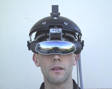
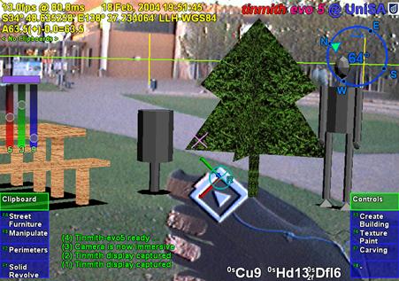

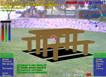
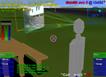
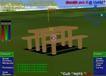
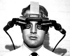
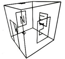
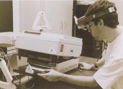
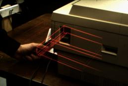

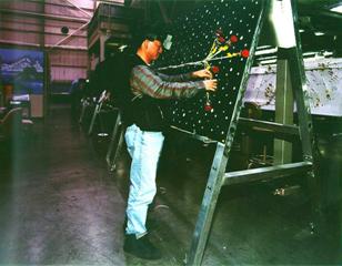
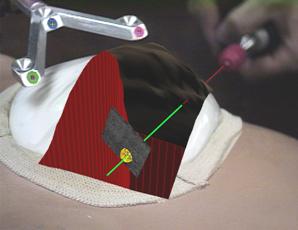

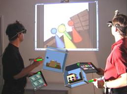
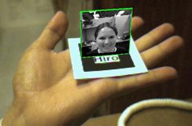
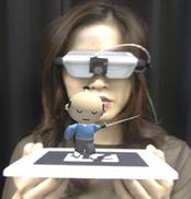
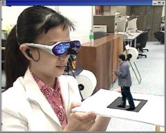
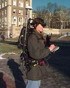
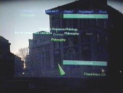
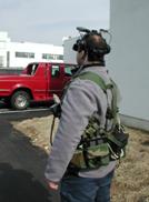
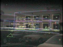
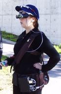
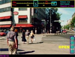
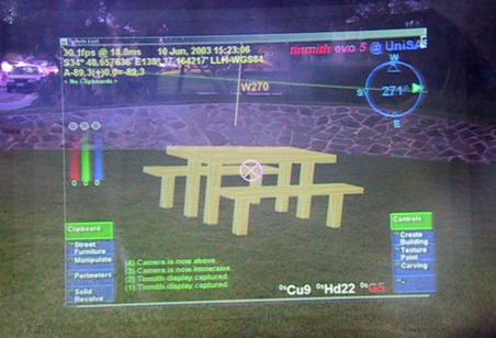

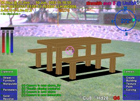
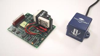
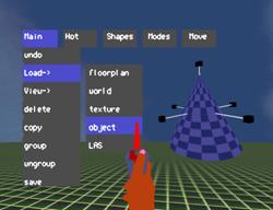
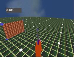
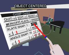
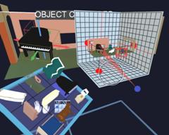
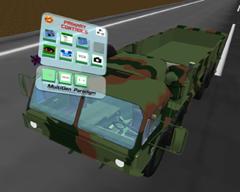
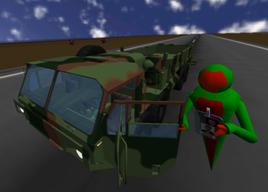
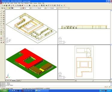

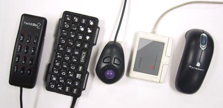


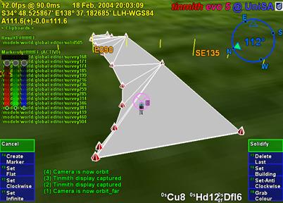
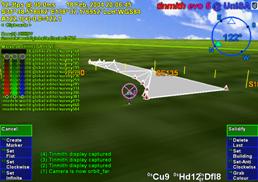
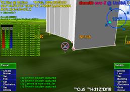

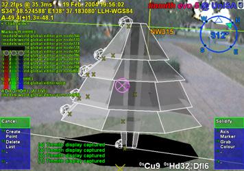
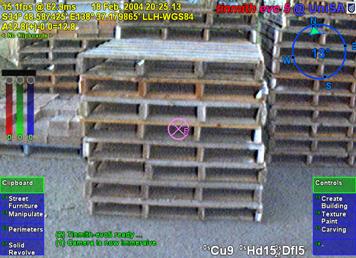
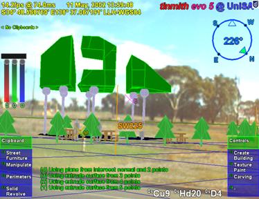
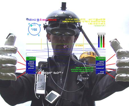
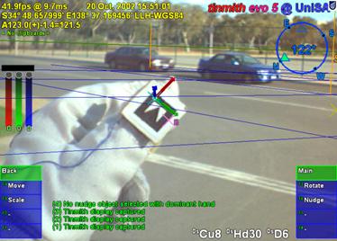
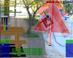 2
2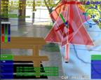 3
3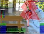 4
4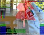
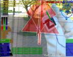 6
6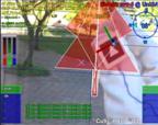 7
7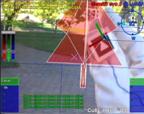 8
8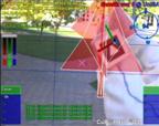
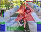 2
2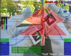 3
3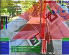 4
4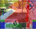
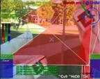 6
6 7
7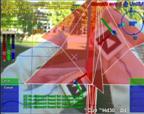 8
8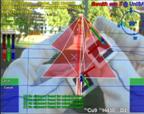
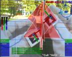 2
2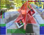 3
3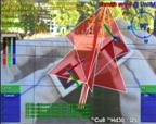 4
4
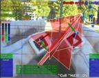 6
6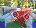 7
7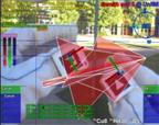 8
8